DHCP through L3 Etherchannel

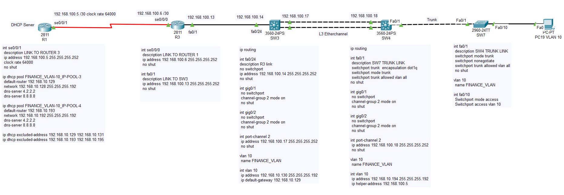
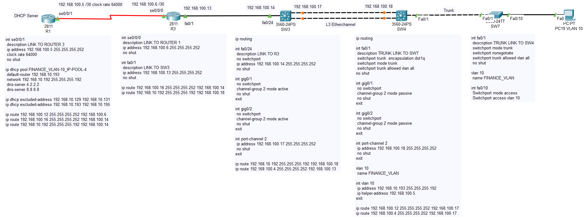
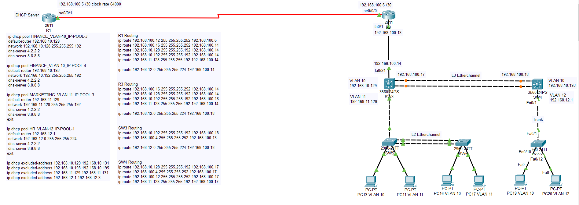
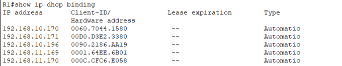
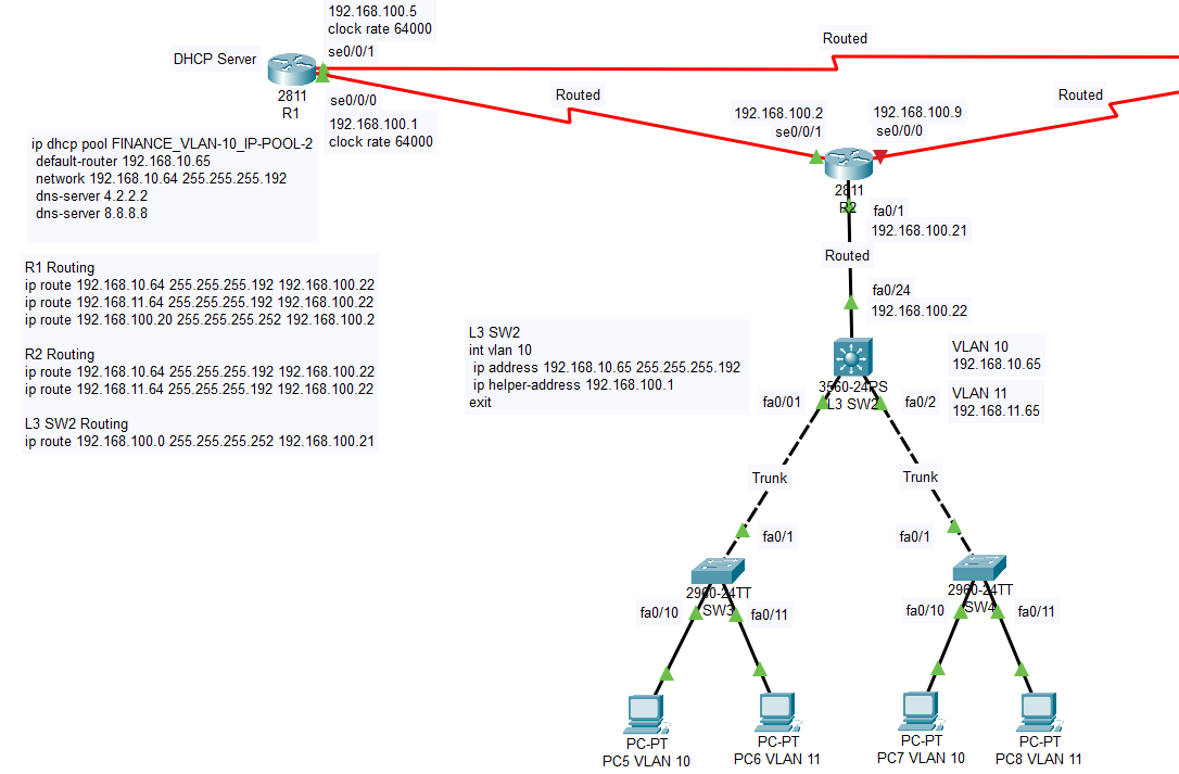
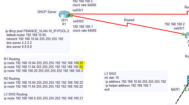
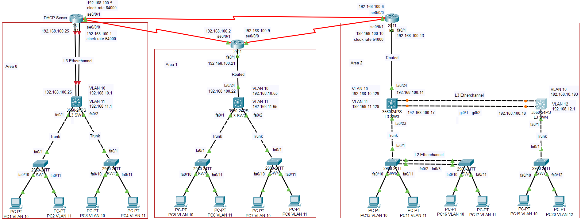
Hello, I configured a network using packet tracer with 3 routers and layer 2 and layer 3 switches. Router 1 has DHCP configured. On Router 3, I added a layer 3 switch and connect it via etherchannel to another layer 3 switch, then to a layer 2 switch where 3 hosts are connected. All the hosts in the network are receiving DHCP except for the hosts connected to the layer 2 switch via the L3 etherchannel switch 4. It seems like I am missing some VLAN configuration on L3 SW 4, but I am not sure. Also how can I verify if the etherchannel is properly configured and working? Below is part of the config, if someone can please advise, greatly appreciate it, thanks.


ROUTER 1

!
int se0/0/1
description LINK TO ROUTER 3
ip address 192.168.100.5 255.255.255.252
clock rate 64000
no shut
exit
!
!
ip dhcp pool FINANCE_VLAN-10_IP-POOL-3
default-router 192.168.10.129
network 192.168.10.128 255.255.255.192
dns-server 4.2.2.2
dns-server 8.8.8.8
exit
!
!
ip dhcp pool MARKETTING_VLAN-11_IP-POOL-3
default-router 192.168.11.129
network 192.168.11.128 255.255.255.192
dns-server 4.2.2.2
dns-server 8.8.8.8
exit
!
!
ip dhcp pool HR_VLAN-12_IP-POOL-3
default-router 192.168.12.65
network 192.168.12.64 255.255.255.224
dns-server 4.2.2.2
dns-server 8.8.8.8
exit
!
ip dhcp pool ENGINEERING_VLAN-13_IP-POOL-1
default-router 192.168.13.1
network 192.168.13.0 255.255.255.192
dns-server 4.2.2.2
dns-server 8.8.8.8
exit
!
ip dhcp excluded-address 192.168.10.129 192.168.10.131
ip dhcp excluded-address 192.168.11.129 192.168.11.131
ip dhcp excluded-address 192.168.12.65 192.168.12.67
ip dhcp excluded-address 192.168.13.1 192.168.13.3
!
------------------------------------------------------------------------------------------------------------------------------------
ROUTER 3
------------------------------------------------------------------------------------------------------------------------------------
int se0/0/0
description LINK TO ROUTER 1
ip address 192.168.100.6 255.255.255.252
no shut
exit
!
int fa0/1
no shut
exit
!
int fa0/1.10
description VLAN 10
encapsulation dot1Q 10
ip address 192.168.10.129 255.255.255.192
ip helper-address 192.168.100.5
!
int fa0/1.11
description VLAN 11
encapsulation dot1Q 11
ip address 192.168.11.129 255.255.255.192
ip helper-address 192.168.100.5
!
int fa0/1.12
description VLAN 12
encapsulation dot1Q 12
ip address 192.168.12.65 255.255.255.224
ip helper-address 192.168.100.5
!
int fa0/1.13
description VLAN 13
encapsulation dot1Q 13
ip address 192.168.13.1 255.255.255.192
ip helper-address 192.168.100.5
------------------------------------------------------------------------------------------------------------------------------------
L3 SW 3 ETHERCHANNEL LINK TO SW 4
------------------------------------------------------------------------------------------------------------------------------------
ip routing
!
int gig0/1
no switchport
channel-group 2 mode on
no shut
exit
!
int gig0/2
no switchport
channel-group 2 mode on
no shut
exit
!
int port-channel 2
ip address 192.168.100.13 255.255.255.252
no shut
exit
!
int fa0/1
description L2 SW TRUNK LINK
switchport trunk encapsulation dot1q
switchport mode trunk
switchport trunk allowed vlan all
no shut
exit
!
int fa0/24
description ROUTER LINK
switchport trunk encapsulation dot1q
switchport mode trunk
switchport trunk allowed vlan all
no shut
exit
!
vlan 10
name FINANCE_VLAN
int vlan 10
ip address 192.168.10.130 255.255.255.192
ip default-gateway 192.168.10.129
!
vlan 11
name MARKETTING_VLAN
int vlan 11
ip address 192.168.11.130 255.255.255.192
ip default-gateway 192.168.11.129
!
vlan 12
name HR_VLAN
int vlan 12
ip address 192.168.12.66 255.255.255.224
ip default-gateway 192.168.12.65
!
vlan 13
name ENGINEERING_VLAN
int vlan 13
ip address 192.168.13.2 255.255.255.192
ip default-gateway 192.168.13.1
exit
------------------------------------------------------------------------------------------------------------------------------------
L3 SW 4 ETHERCHANNEL LINK TO SW 3 & L2 SW 7
------------------------------------------------------------------------------------------------------------------------------------
ip routing
!
int gig0/1
no switchport
channel-group 2 mode on
no shut
exit
!
int gig0/2
no switchport
channel-group 2 mode on
no shut
exit
!
int port-channel 2
ip address 192.168.100.14 255.255.255.252
no shut
exit
!
int fa0/1
description SW7 L2 TRUNK LINK
switchport trunk encapsulation dot1q
switchport mode trunk
switchport trunk allowed vlan all
no shut
exit
------------------------------------------------------------------------------------------------------------------------------------
L2 SW 7
------------------------------------------------------------------------------------------------------------------------------------
int fa0/1
switchport mode trunk
switchport nonegotiate
switchport trunk allowed vlan all
no shut
exit
!
vlan 10
name FINANCE_VLAN
!
int fa0/10
Switchport mode access
Switchport access vlan 10
Exit
!
vlan 11
name MARKETTING_VLAN
!
int fa0/11
Switchport mode access
Switchport access vlan 11
Exit
!
vlan 13
name HR_VLAN
!
int fa0/13
Switchport mode access
Switchport access vlan 13
Exit
!

strong text

Hello Dinesh

There are two issues that are creating your problem. First, it seems that there is no default gateway for the network segments that are being served by L2S7. This switch connects via a trunk to the L3SW4 switch, but there are no Layer 3 VLAN interfaces (SVIs) there to act as default gateways.

Secondly, these SVIs must be configured with the ip-helper-address command so that any DHCP requests will be sent back to the DHCP server. In addition, you will have to add the ip-helper-address command on the Layer 3 etherchannel interface of L3SW3 as well, so that it too, in turn, can relay the DHCP messages to the DHCP server.

Another solution would be to make the link between L3SW3 and L3SW4 a Layer 2 Etherchannel. This will make R3 the default gateway of each VLAN, which already has the ip-helper-address configuration, so no additional configuration is necessary.

Now just a general comment about the topology, the fact that you are using the same VLAN numbers for subnets that are actually distinct from each other, can be confusing. At first I thought that all of the VLAN 10s across the board had the same subnet, and are separated by Layer 3 infrastructure, something that would not function correctly. But then I realized that you did not include all of the DHCP subnets provided by R1. Although the configuration is correct, I suggest you use different VLAN numbers to distinguish between the various VLANs across the whole network.

I hope this has been helpful.

Laz

1 Like

Laz,

Router 1 serial interface is connected to router 3 serial interface, with router 1 ip being
192.168.100.5, and router 3 ip being 192.168.100.6

Using VLAN 10 as reference:

On router 1, DHCP pool 3 for VLAN 10 is configured for network 3 as:

ip dhcp pool FINANCE_VLAN-10_IP-POOL-3
default-router 192.168.10.129
network 192.168.10.128 255.255.255.192
dns-server 4.2.2.2
dns-server 8.8.8.8

On router 3, fa0/1, the sub-interface for VLAN 10 is configured with the ip helper-address as:

int fa0/1.10
description VLAN 10
encapsulation dot1Q 10
ip address 192.168.10.129 255.255.255.192
ip helper-address 192.168.100.5

On SW3 VLAN 10 is configured with ip address 192.168.10.130

On SW4 VLAN 10 is configured with ip address 192.168.10.131

SW3 is connected to SW4 via layer 3 etherchannel using port-channel ip addresses 192.168.100.13 255.255.255.252 and 192.168.100.14 255.255.255.252

SW3 is also connected to SW5, 2960 switch and the hosts are receiving ip’s.

SW4 is connected to a SW7, 2960 switch and the hosts are not receiving ip’s.

I made the changes below, but the hosts connected to SW7 still not getting DHCP:

SW3 - 3560

ip routing
!
vlan 10
name FINANCE_VLAN
int vlan 10
ip address 192.168.10.130 255.255.255.192
ip default-gateway 192.168.10.129
!
int gig0/1
no switchport
channel-group 2 mode on
no shut
exit
!
int gig0/2
no switchport
channel-group 2 mode on
no shut
exit
!
int port-channel 2
ip address 192.168.100.13 255.255.255.252
ip helper-address 192.168.100.5
no shut
exit

SW4 -3560

ip routing
!
int gig0/1
no switchport
channel-group 2 mode on
no shut
exit
!
int gig0/2
no switchport
channel-group 2 mode on
no shut
exit
!
int port-channel 2
ip address 192.168.100.14 255.255.255.252
*ip helper-address 192.168.100.5
no shut
exit
!
int fa0/1
description TRUNK LINK TO SW7
switchport trunk encapsulation dot1q
switchport mode trunk
switchport trunk allowed vlan all
no shut
exit
!
vlan 10
name FINANCE_VLAN
int vlan 10
ip address 192.168.10.131 255.255.255.192
ip helper-address 192.168.100.5
ip default-gateway 192.168.10.129
SW7 - 2960

int fa0/1
description TRUNK LINK TO SW4
switchport mode trunk
switchport nonegotiate
switchport trunk allowed vlan all
no shut
exit
!
vlan 10
name FINANCE_VLAN
!
int fa0/10
Switchport mode access
Switchport access vlan 10
Exit
!

I think the layer 3 etherchannel is working, but still trying to get the hosts connected to L2 SW7 to obtain IP addresses via DHCP, please advise, thanks

Hello Dinesh

There are a few issues with this topology. Take a look at this diagram:

The green area may be separated into three VLANs, but it is all Layer 2. It represents three distinct network segments, one for each VLAN, that span the whole green area. This means that all of the PCs have one of the subinterfaces on R3 as their default gateway. The IP helper address configured on R3 allows them to find the DHCP server. I know that this is all Layer 2 because both ports Fa0/1 and Fa0/24 on SW3 are configured as trunks. As a results any DHCP messages sent from any of the PCs will reach R3.

In the same way, the yellow area is also composed of three distinct network segments, one for each VLAN. But between the yellow area and the subinterface on R3, there intervenes another Layer 3 area, (the red oval) which is the L3 Etherchannel. So the three PCs on SW7 must use the SVI on SW4 as the default gateway, and in order to reach the rest of the network, routing must be employed.

Now you have correctly implemented VLAN 10 SVI on SW4 with an IP helper address, as well as the routed etherchannel port on SW3. However, there are still a couple of problems. Let’s take VLAN 10 as the reference.

  1. The IP address of the GW for VLAN 10 is 192.168.10.131/26. But this address is in the same subnet as that used by VLAN 10 in the green area. Each distinct network segment must have non overlapping IP address spaces. Otherwise routing will fail.
  2. Even if the IP address of the GW for VLAN 10 was in a different subnet, SW4 must have some routing configured so that it knows how to reach the configured IP helper address. Once a DHCP packet reaches the GW of VLAN 10, SW4 will have to send the DHCP request to the IP helper address of 192.168.100.5. Does it know how to get there? Is there routing configured in SW4 for that? In the same way, SW3 must also have this routing information configured so when it receives any packets from SW4, it knows where to send them.
  3. The IP helper address configuration on the etherchannel port on SW4 is not necessary, since no DHCP requests should be expected on this interface, since there are no hosts in the 192.168.100.12/30 address space. This will not cause a malfunction, but it is simply not needed.

It is important to note that the networks on SW7 are the only networks that are separated from the DHCP server by another L3 area. For this reason, routing must be employed on all intervening network devices (SW3 and SW4) between the network segments. And for this reason too, you require non overlapping IP address spaces for the VLANs being served by SW7. May I suggest to use 192.168.10.192/26 for VLAN 10?

I hope this has been helpful!

Laz

1 Like

Hi Laz, thank you for the advice. As you can see I am still up trying to figure this out. Is it possible if you can send me a config setting for SW3 (in relation to SW4 & SW7), and a config setting for SW4 and SW7 (if required, I have the ports and vlans configured for SW7, but if there is any other setting). My brain is giving up here lol. Yea you can use any ip for VLAN 10, thanks

Hello Dinesh

I know how it feels!! :crazy_face: Let me try to get you on the right track.

Let’s start with the three VLANs that are hanging off of SW7. You have to choose a subnet for each of these VLANs that is not overlapping with any other segment. I am assuming that PC19 is on VLAN 10, PC20 is on VLAN 11, and PC21 is on VLAN 13.

A note here on the VLAN numbers. You are using the same VLAN numbers (except for 13) as those found on other parts of the network, but these are different network segments. This is technically correct, but can becoming confusing, because the same VLAN seems to indicate the same subnet… But since these are on different segments, they must have different subnets.

I suggest you use the following subnets for these VLANs:

VLAN10 192.168.10.192/26
VLAN11 192.168.11.192/26
VLAN 13 192.168.13.192/26

These subnets are in addition to those you already have on your diagram.

Now SW4 should be configured with:

  • Three SVIs, one for each of these VLANs, configured as the default gateways of these subnets. I suggest 192.168.10.193, 192.168.11.193 and 192.168.13.193 respectively.
  • these SVIs should be configured with the IP helper address of 192.168.100.5
  • the switch should have routing configured so it can find all the other remote networks including:
    192.168.100.0/30
    192.168.100.4/30
    192.168.100.8/30
    192.168.100.12/30
    192.168.10.0/26
    192.168.10.64/26
    192.168.10.128/26
    192.168.10.192/26

And so on for the rest of the VLANs… This must be done so that all hosts will be able to reach all other hosts. But it is also necessary in order to allow SW4 to reach the DHCP server for the IP helper address relaying of DHCP messages.

I believe that SW3 is correct as it is. The only thing you need to add is routing to the remote networks. Specifically, to those networks mentioned above, but also to the three networks hanging off of SW4, that is, VLANs 10, 11, and 13 as described above. The IP helper address on this is fine.

Now just another comment about your other networks. On SW1 and SW2, you have configured SVIs with IP addresses. These are not being used at all. No traffic is being routed to these IP addresses. So you can even remove these IP addresses from these interfaces and conserve addresses. You may want to keep only one for the purposes of connecting to the CLI. These switches are actually only functioning at Layer 2 as far as the topology goes. This is because all PCs are on the same network segment as the corresponding subinterface on R1 and R2. Only SW3 requires routing, since we are routing traffic over a Layer 3 Etherchannel to reach the networks off of SW4.

I hope this has been helpful!

Laz

Hi Laz, thanks for replying, I am taking it one step at a time :slight_smile:

Since I will be using the 192.168.10.192 network for VLAN 10, I am assuming I have to create a DHCP pool as well on R1:

R1

ip dhcp pool FINANCE_VLAN-10_IP-POOL-4
default-router 192.168.10.193
network 192.168.10.192 255.255.255.192
dns-server 4.2.2.2
dns-server 8.8.8.8
exit

Now where should I put this VLAN 10, on SW4 or SW7, and what would be the default gateway, 192.168.10.130?

Should it be configured like below:

vlan 10
name FINANCE_VLAN
int vlan 10
ip address 192.168.10.194 255.255.255.192
ip default-gateway 192.168.10.130
ip helper-address 192.168.100.5

Hello Dinesh

Yes, that is correct. And your configuration looks good.

I assume you mean where should the VLAN interface, or SVI be configured? That should be on SW4. I’m assuming SW7 is to function only on Layer 2. Now if you use IP routing, you won’t need the ip default-gateway command. I would suggest that you use routing instead, as it is more flexible. If you do use the ip default-gateway command, you would use 192.168.100.13 as the default gateway. This is the IP address of the next hop router, which is SW3.

I hope this has been helpful!

Laz

Hi Laz,
I am still not getting an ip for PC19 in VLAN 10 on SW7. I tried simplifying the network. I removed the sub interfaces on R1 & R3. I am thinking ip routes have to be configured.
I am not sure if it is correct or sufficient to use the two ip routes command below:
SW4: ip route 192.168.100.4 255.255.255.252 192.168.100.13
R1: ip route 192.168.100.16 255.255.255.252 192.168.100.14
Please advice, thanks

Hello Dinesh

Here are my comments about your topology:

  1. SW7 looks fine.
  2. For SW4, the VLAN 10 interface should have an IP address of 192.168.10.193 since this is also the default gateway that you have configured for the corresponding DHCP pool in R1. IP helper address is good.
  3. On SW4 you must also configure routing so that this switch can reach all of the remote networks. If you employ static routing, it should look something like this:

ip route 192.168.100.12 255.255.255.252 192.168.100.17
ip route 192.168.100.4 255.255.255.252 192.168.100.17

  1. SW3 doesn’t need the VLAN 10 interface configuration for this topology. It doesn’t affect it, but it is not needed.
  2. SW3 also requires routing. The default-gateway command is not enough to allow this device to route to all remote networks. For example, any packets destined to the 192.168.10.192/26 network will be dropped. The default gateway configuration must be removed and replaced with the following static routing commands:

ip route 192.168.10.192 255.255.255.192 192.168.100.18
ip route 192.168.100.4 255.255.255.252 192.168.100.13

  1. Finally, the ip dhcp pool FINANCE_VLAN-10_IP-POOL-3 is unnecessary in this topology since there is no such subnet.

I hope this has been helpful!

Laz

Hi Laz,
Thanks for the info. I tried it, but still no ip on PC 19. Should I use the ip route command on R1:
ip route 192.168.100.16 255.255.255.252 192.168.100.14 ? I also notice when I hover the mouse over SW3 & SW4 its saying the port channel is in vlan 1, and at the bottom its saying vlan 1 link down. I am changing the etherchannel to LACP - active mode.

I deleted the switches, add them back and re-configured the etherchannel to LACP but its showing the port-channel link as down, even though the lights are green.
When I use these commands:
int gig0/1
no switchport
channel-group 2 mode active
no shut
exit

int gig0/2
no switchport
channel-group 2 mode active
no shut
exit

instead of the range, int gig0/1 - 2, the port channel link shows as up, as is shown in the last snapshot below, but the lights remain orange. Also if I restart packet tracer the link goes down and the lights turn to green and I have to re-enter the command above for the link to show as up, and the lights would turn back orange. The etherchannel must be mis-configured somehow. This is really confusing.

Hello Dinesh

I tried labbing this up in packet tracer. The truth is that the Etherchannel does appear to be misbehaving as I too get amber lights on the etherchannel.
image
However, doing a show etherchannel summary shows that the etherchannel is working correctly:

Switch#show etherchannel summary 
Flags:  D - down        P - in port-channel
        I - stand-alone s - suspended
        H - Hot-standby (LACP only)
        R - Layer3      S - Layer2
        U - in use      f - failed to allocate aggregator
        u - unsuitable for bundling
        w - waiting to be aggregated
        d - default port


Number of channel-groups in use: 1
Number of aggregators:           1

Group  Port-channel  Protocol    Ports
------+-------------+-----------+----------------------------------------------

2      Po2(RU)           LACP   Gig0/1(P) Gig0/2(P) 
Switch#

So I wouldn’t be too worried about how it is displayed there.

Remember that you have made the portchannel a Layer 3 interface, so the VLAN indication here doesn’t mean anything. If you can ping, you’re fine. I see the same in my configuration as well.

What is missing in your topology is what you stated above about routing on R1 and R2. You have to make sure that all routers can reach all networks. Your SW3 and SW4 routing are fine, but you need to add to both R1 and R2. I suggest you do the following:

  1. Configure the PC with a static IP address.
  2. Progressively ping each of the routers from the PC along the path like so:
    ping 192.168.10.193 (SW4 VLAN 10 interface)
    ping 192.168.100.17 (SW3 Portchannel interface)
    ping 192.168.100.13 (R2 Fa0/1 interface)
    ping 192.168.100.5 (R1 Se0/0/1 interface)
    Wherever you find that the ping fails, you can troubleshoot connectivity and routing
  3. Once you get end to end connectivity, configure the DHCP server on R1 and the helper address on VLAN 10 interface of SW4, and then configure the PC to function with DHCP

This is the procedure I followed, and I troubleshot all my errors. It took a while for the DHCP helper address to kick in, so the host didn’t get an IP address immediately. I had to disconnect and connect it again.

I could send you my topology, but I think it would be more useful for you to work this out on your own. If you still have trouble however, I’ll save it and send it to you.

I hope this has been helpful!

Laz

Hi Laz,
Everytime I restart packet tracer the lights on the etherchannel links lights up green, but the port channel (po2) link is showing as down, and I have to re-enter the etherchannel link configuration:

int gig0/1
no switchport
channel-group 2 mode active
no shut
exit

int gig0/2
no switchport
channel-group 2 mode active
no shut
exit

When I re-enter it on SW3 the lights remain green, but as soon as I re-enter it on SW4 it turns orange, but shows the links as being up, then after about 5 mins PC 19 gets an ip.

I am not sure why I have to re-enter the etherchannel link configuration everytime I restart packet tracer, and why the link lights are turning orange.
I am wondering if spanning tree, port fast or something else have to be configured.

If I do sh sp on SW3 its saying no spanning tree instance exists, but on SW4 it says:

SW4#sh sp
VLAN0001
Spanning tree enabled protocol ieee
Root ID Priority 32769
Address 0060.3E59.5B2C
Cost 19
Port 1(FastEthernet0/1)
Hello Time 2 sec Max Age 20 sec Forward Delay 15 sec

Bridge ID Priority 32769 (priority 32768 sys-id-ext 1)
Address 0090.2B48.2014
Hello Time 2 sec Max Age 20 sec Forward Delay 15 sec
Aging Time 20

Interface Role Sts Cost Prio.Nbr Type


Fa0/1 Root FWD 19 128.1 P2p

VLAN0010
Spanning tree enabled protocol ieee
Root ID Priority 32778
Address 0060.3E59.5B2C
Cost 19
Port 1(FastEthernet0/1)
Hello Time 2 sec Max Age 20 sec Forward Delay 15 sec

Bridge ID Priority 32778 (priority 32768 sys-id-ext 10)
Address 0090.2B48.2014
Hello Time 2 sec Max Age 20 sec Forward Delay 15 sec
Aging Time 20

Interface Role Sts Cost Prio.Nbr Type


Fa0/1 Root FWD 19 128.1 P2p

I configured the ip route commands, I think they are correctly entered as I can ping end to end, after re-entering the etherchannel link configuration and wait for the PC to get the ip.

Hello Dinesh

This makes sense because SW3 is not connected to any other switches via Layer 2. All of its connections are L3, so no STP is functioning. SW4 however has a L2 link with SW7 so STP is running. There is no issue with spanning tree.

I have found that when I open packet tracer, both links between SW3 and SW4 are now green. But the portchannel interface is indeed down. I too have to put in those commands again to get it to work. So it looks like it’s a packet tracer issue.

So then it looks like it worked!! That’s great!

I hope this has been helpful!

Laz

Hi Laz,
Thanks alot to get this working. I did some more config on the network. Everything is working fine except PC20 in VLAN 12 is not getting an ip. From R1 I can ping VLAN 12, 192.168.12.1 on L3 SW4.
I am not sure if did something incorrectly, or if I have to enter some more configuration to get PC 20 on VLAN 12 to obtain an IP. Under DHCP binding I didn’t notice any info for 192.168.12, not sure if it is required, since the remaining networks are listed, or I guess that is because an ip hasn’t been issued for that network as yet.
After I get this through, I will remove all static routes and most likely implement OSPF. Here is the design, can you say why PC20 is not getting an ip, thanks


DHCP Binding

Hi Laz,
I took some aspirin but it didn’t help lol. I added a next router and config the network for DHCP, or at least so I thought. The PC’s are not getting IP’s. I am not sure what I did wrong, or what I didn’t do. From R1 I can ping 192.168.100.22, 192.168.10.65, 192.168.11.65. From L3 SW2 I can ping 192.168.100.2, 192.168.100.1, so I am assuming the ip route commands are ok. I am not sure what’s missing or if I mistakenly entered something somewhere that’s not suppose to be there.
Please take a look and let me know what you think, thanks.

On R1:
int se0/0/0
description LINK TO ROUTER 2
ip address 192.168.100.1 255.255.255.252
clock rate 64000
no shut

Hello Dinesh

Since you can ping from R1 to the the VLAN12 interface on SW4, then routing is not the problem. The first thing that comes to mind is the ip-helper address. Remember that the ip-helper address must be configured on each interface of SW4 that is used as a default gateway for subnets you want to provide IP addresses via DHCP. So if you have the IP helper address on the VLAN 10 interface of SW4, you must also have this command on VLAN 12 of SW4.

Since you have connectivity between R1 and the VLAN 12 interface of SW4, you should also check connectivity all the way to the PC. Put in a static IP address on PC20 (say 192.168.12.5 with a default gateway of 192.168.12.1) and see if you have end to end connectivity with R1. If not, then you should check the VLAN configuration on SW7 and the configuration of the trunk to SW4 as well.

The problem you’re looking for will most likely be one of the two mentioned above. It’s great to see that you are persevering, and that is an excellent trait to have for certification! Let me know your progress.

I hope this has been helpful!

Laz

Hello again Dinesh

At first glance, everything seems to be in order. I suggest you use the same troubleshooting strategy and first make sure that you have end to end (PC to R1) routing successfully configured by configuring a static IP for the PCs and attempting a ping. Use both ping and traceroute to see where the problem may be.

Ah, but as I take a closer look, I see a typo:


Should that not be “.2” instead of “.22”? I don’t know if that’s in your config or just your copy past, but take a look. With this routing, you shouldn’t be able to ping 192.168.10.65, but in any case, I suggest you continue the troubleshooting strategy I mentioned above.

So if routing is OK, then you should then verify the ip helper address commands. Try these out and let us know your results!

I hope this has been helpful!

Laz

Hi Laz,
Thanks for the compliments. I wrote the script but didn’t copy and paste them all, so I re-pasted and everything works lol.
I will work on network 1, R1, now, configuring DHCP through the etherchannel between R1 and L3 SW1, then after that will remove all static routes, and implement OSPF.