The command crypto isakmp key command is used to configure a preshared authentication key. The crypto keyring command, on the other hand, is used to create a repository of preshared keys. The keyring is used in the ISAKMP profile configuration mode. The ISAKMP profile successfully completes authentication of peers if the peer keys are defined in the keyring that is attached to this profile.
The term keyring is used to denote that the keyring includes multiple preshared keys, much like a physical keyring contains many keys. For more information about creating and maintaining keyrings, take a look at the following Cisco documentation.
The "Encapsulating Security Payload section of the capture is the encrypted portion of the payload that cannot be read by default on Wireshark. However, it is possible to have Wireshark decypher the contents of that portion of the payload. In order to do this, you must:
Navigate to Edit → Preferences → Protocol → ESP
Select the check box “Attempt to detect/decode encrypted ESP payload”
Click on Edit in “ESP SA” and click “New”
Enter the following information:
Source and destination IP
IP SPI
Encryption and authentication algorithm
Encryption and authentication key for both directions
Once that info is in place, you should find that the packets are decrypted and they can be read.
An example of this process can be found at this Wireshark Q&A page.
This particular example examines the ESP encrypted packets from a Linux device, but the concept is the same.
Really appreciate for the clarifications.I am sorry that I did not clearly describe the problem before.My data package comes from GNS3 emulation environment (Windows),At present, I am troubled by the “4.Encryption and authentication key for both directions” you mentioned.I wonder if GNS3 provides instructions for debugging or viewing key strings, or if it has to go through 3rd party tools like the strongSwan for Liunx…
Thanks for your clarification. For the encryption and authentication key for both directions, we’re talking about the key found in the command crypto isakmp key DMVPN_KEY address 0.0.0.0. For both the spokes and the hub, the key is DMVPN_KEY, at least in this lesson.
Now if you don’t know this key and you want to find out what it is, so that you can see what’s in the ESP section of the packet, well then you have a problem. . If you don’t have that information, I’m afraid that it won’t be possible to determine it. This is the expected behaviour, and it shows you how security can mitigate against people trying to read data that they’re not “supposed” to, even if they capture packets on your network. The only way to do it is to determine the key that was used and to do that, you will need to access the devices that are terminating the IPSec tunnel.
I was trying to make sure I understood this correctly. This lesson states the following:
Configure a pre-shared key for each “router pair” you have: this means we use a unique key for hub-spoke1, hub-spoke2 and spoke1-spoke2. This is secure but it’s not a very scalable solution, the more spoke routers we add to the network, the more keys we have to configure.
does this mean you have multiple lines of the same command with different address of the destination device?
Such as this: crypto isakmp key DMVPN_KEY address 1.1.1.1 (this will be for hub) crypto isakmp key DMVPN_KEY address 3.3.3.3 (this will be for spoke 3) crypto isakmp key DMVPN_KEY address 3.3.3.3 (this will be for spoke 4)
meaning if we was adding this for say spoke 2 and we wanted to not use the wildcard of 0.0.0.0 then we would have multiple lines on our spoke 2 config for each of the spokes and the hub?
Then on those devices it would be same as well?
Just wanted to make sure I understood this as I tried to search for examples on internet but didnt find a good one.
Yes, that is the case. The amazing thing is that in Cisco’s documentation, it explicitly states that:
It is highly recommended that you do not use wildcard preshared keys because the attacker will have access to the VPN if one spoke router is compromised.
Even so, in all of their examples, they use a wildcard preshared key.
But your syntax is correct for configuring individual keys for each pair of routers in the DMVPN topology.
I can see that we will need ACL when configuring site-to-site IPsec VPN.
However for DMVPN over IPsec, is there an exception or do we need to configure ACL too ?
When implementing IPSec on a regular GRE tunnel, one of the things you must create is a crypto map, which tells IPSec what traffic must be encrypted. The crypto map references an access list and matched traffic will be encrypted. This kind of configuration is detailed in the following lesson:
Now, a newer method of configuration for IPSec tunnels, known as virtual tunnel interfaces (VTIs) was created to simplify configuration especially if you have many remote peers. Instead of crypto maps, this uses crypto profiles used for tunnel interfaces. This kind of configuration is detailed in the following lesson:
Now, when applied to DMVPN, you use VTIs, and crypto profiles to enable IPSec over DMVPN, thus no access list is necessary to identify traffic.
I’ve question, as always, i’ve replicated this lab on gns3.
When i do show crypto isakmp sa on spokes (after ping ) i can see only a single SA.
SPOKE1#show crypto isakmp sa
IPv4 Crypto ISAKMP SA
dst             src             state          conn-id status
192.168.123.1   192.168.123.2   QM_IDLE           1001 ACTIVE

IPv6 Crypto ISAKMP SA

SPOKE2#show crypto isakmp sa
IPv4 Crypto ISAKMP SA
dst             src             state          conn-id status
192.168.123.1   192.168.123.3   QM_IDLE           1001 ACTIVE

IPv6 Crypto ISAKMP SA
If I configure a DMVPN Phase 3 I can see the same output of Rene.
SPOKE2#show crypto isakmp sa
IPv4 Crypto ISAKMP SA
dst             src             state          conn-id status
192.168.123.3   192.168.123.2   QM_IDLE           1002 ACTIVE
192.168.123.2   192.168.123.3   QM_IDLE           1003 ACTIVE
192.168.123.1   192.168.123.3   QM_IDLE           1001 ACTIVE

IPv6 Crypto ISAKMP SA

SPOKE2#
I see that Rene didn’t configure a DMVPN Phase3 on this lesson but he get 3 security associations entry in spokes routers.
I went and labbed this up on CML and replicated Rene’s topology which uses DMVPN Phase 2 which was used in the lab. I too got three security associations like so:
Spoke1#show crypto isakmp sa
IPv4 Crypto ISAKMP SA
dst             src             state          conn-id status
192.168.123.2   192.168.123.3   QM_IDLE           1003 ACTIVE
192.168.123.3   192.168.123.2   QM_IDLE           1002 ACTIVE
192.168.123.1   192.168.123.2   QM_IDLE           1001 ACTIVE
What I did find interesting however is as soon as I performed the ping, I and issued the above command, I initially only got two associations:
Spoke1#show crypto isakmp sa
IPv4 Crypto ISAKMP SA
dst             src             state          conn-id status
192.168.123.3   192.168.123.2   QM_IDLE           1002 ACTIVE
192.168.123.1   192.168.123.2   QM_IDLE           1001 ACTIVE
Only after a couple of seconds did I get the third. Now for both DMVPN Phase 2 and 3, this is expected, since we have direct spoke-to-spoke communication, and the IPSec secures a multipoint GRE tunnel. Therefore you should see an SA for communication with the hub, and communication with the other spoke.
The third SA comes in a little later when there is communication initiated by Spoke 3 towards Spoke 1. You can see that the src IP is that of Spoke 3 while the dst IP is that of Spoke 1. This may be a routing update via RIP that initiates it or some other control plane process.
Beyond that I can’t see why you only get one SA other than GNS3 may be acting up again!
So because this is a Phase 2 DMVPN example, this is why we see the SA being created between spoke 1 and 2 when a ping to the loopback is created? Else, on a phase 1 you would only see the SA to the HUB correct?
Thank you for the great explanation. I have dug and dug and dug through Cisco and other documentation and just get more and more confused on IPSEC config and this helped greatly with a great example to help me get through adding a new device to an existing HUB/SPOKE DMVPN setup and to understand the steps, than just copy/paste existing config!
Why would using tunnel mode add overhead to DMVPN?
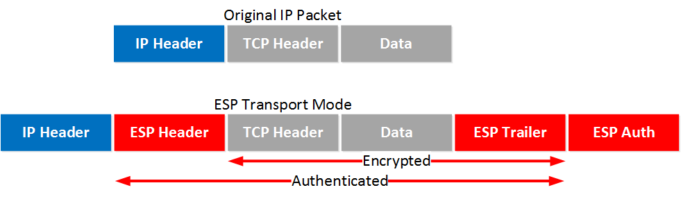
I understand that the transport mode does not encrypt the original IP header (Private Addresses) and preserves it, so what would happen to the packets from the hosts that go from LAN to LAN that travel through the tunnel (Public Addresses)?
Tunnel mode always adds more overhead than transport mode, regardless of whether it is a DMVPN implementation or otherwise. Indeed transport mode does not encrypt the original IP header and preserves it. However tunnel mode encrypts the header, which necessitates a new IP header to be prepended, which is where the extra overhead is found.
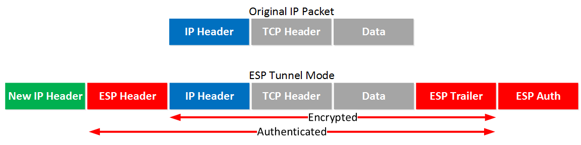
Using ESP, this is what transport mode looks like:
You can see that in tunnel mode we are preserving the original IP header and encapsulating the whole IP packet within the ESP header and a new IP header. It is this new IP header that results in the additional overhead. The above diagrams are taken from the following lesson which further describes these concepts in more detail:
So in the DMVPN solution, what is preserved when setting the transport mode is the external GRE IP header, otherwise there would be 2 external IP headers (GRE and IPsec). I am right?
If 2 hosts on different LANs (private IPs) communicate, due to the GRE header (public IPs) their packets can travel through the tunnel right?
Yes, you are correct. Transport mode preserves the GRE IP header, meaning it does not encrypt it. Otherwise, there would indeed be two IP headers, one for GRE and one for IPsec.
The original IP header contains the original IP addresses of the source and destination (which are those of the 2 hosts you mention). These hosts will indeed be able to communicate with each other over the GRE tunnel using the GRE header with the public IPs.
In this particular scenario, we are using DMVPN Phase 2. This means that we are creating spoke-to-spoke tunnels, so traffic will go directly from spoke to spoke. However, to create a spoke-to-spoke tunnel, initially, traffic is sent to the hub. Using NHRP, the hub directs all subsequent traffic to be routed directly between spokes.
For multicast traffic, the behavior is similar:
The ip nhrp map multicast command on the hub helps to initially establish multicast traffic flow from the hub to the spokes. When you configure this command, multicast traffic is initially sent to the hub, which then forwards the traffic to the spokes.
Once spoke-to-spoke tunnels are established using NHRP to dynamically discover the public IP address of the other spokes, subsequent multicast traffic can flow directly between the spokes, bypassing the hub. This is possible because of the use of NHRP in a similar manner as with unicast traffic to dynamically discover the public IP addresses of the other spokes and create direct GRE tunnels between them.
When a spoke wants to send multicast traffic to another spoke, it first checks its NHRP cache to see if it has a direct GRE tunnel to the destination spoke. If it does, it will send the traffic directly through that tunnel. If it doesn’t have a direct tunnel, it will send the traffic to the hub, which will then forward it to the destination spoke.
So, once spoke-to-spoke tunnels are created, multicast traffic will not always go via the hub. Instead, it will be sent directly between the spokes, providing a more efficient traffic flow.