Hi,
Regarding filtering with OSPF. Would creating access list that blocks rfc 1918 be somehow solution to this in production network ?
Standard IP access list rfc1918
10 deny 10.0.0.0, wildcard bits 0.255.255.255
20 deny 172.16.0.0, wildcard bits 0.0.15.255 (4 matches)
30 deny 192.168.0.0, wildcard bits 0.0.255.255
40 permit any (3 matches)
On the HUB side you cconfigure default information originate always. On the spoke side just use distribure list to block rfc1918 IP addresses.
Hello Erik
Blocking private IPv4 addresses on the edge of your network is standard security practice. Private addresses are considered part of a set of IPv4 addresses known as bogons, or bogus, or fake IP addresses. (More about bogons here This is typically applied at the network edge, at a firewall, or an edge router. Why? Because you should never receive any routing advertisements about private addresses from the Internet. If you do, then it is suspicious behavior, so these should be blocked.
I’m not sure what you are suggesting here, because in the case of the topology in the lesson, you may have private IPv4 addresses at remote sites that you would want to advertise using OSPF. Any such filtering would cause problems in routing. Such filtering should only be applied on an Internet-facing interface in an incoming direction.
Can you elaborate on your reasoning behind creating such filtering so that we can further respond to your concerns? Thanks!
I hope this has been helpful!
Laz
Thank you amazing explanation as usual
1 Like
Hi Rene,
Why did you change the OSPF area from 0 to 1?
is it because area 0 is only to be used as a backbone area (normal area ) and cannot be used as a stub?
What if we have a multiarea ospf design?
Hello Champion
By definition, a stub area in OSPF cannot be a backbone area. For this reason, in order to configure an OSPF stub area in the DMVPN topology, an area other than area 0 had to be used. Take a look at this lesson for more information on stub areas.
It is possible to create a multi-area OSPF design for a DMVPN topology, however, there must be a reason for it. What do I mean? Well, OSPF should be split into multiple areas in order to make OSPF update messages smaller and to minimize the number of OSPF updates that may be sent over slower links. These factors have to do both with the scale of the network as well as the architecture and topology of the network.
One approach for DMVPN is to put one or more hubs you have into the backbone area, and then assign a different area to each spoke. This is useful when you have large networks with many prefixes behind each of the spokes. Another approach is to put the hub and spoke routers into area 0 and put the LANs that exist behind each spoke into non-backbone areas.
Having said that, if you can have your whole DMVPN topology within a single OSPF area, it is preferrable, since it eliminates the complexity that a multi-area OSPF topology introduces. Unless your network is so large that OSPF begins to slow down, and updates are becoming too large, it would be best to keep everything in one area.
I hope this has been helpful!
Laz
Thanks Laz.
Very much understood!!
Champ
1 Like
Hello, everyone
Rene mentioned in the video that when it comes to OSPF routing, the spoke routers will always learn about all the other networks from the other spoke routers by default because we can’t do any summarization within the area.
Well, why not just put the hub and the spoke routers into a separate area than the networks that reside behind them? Like this:
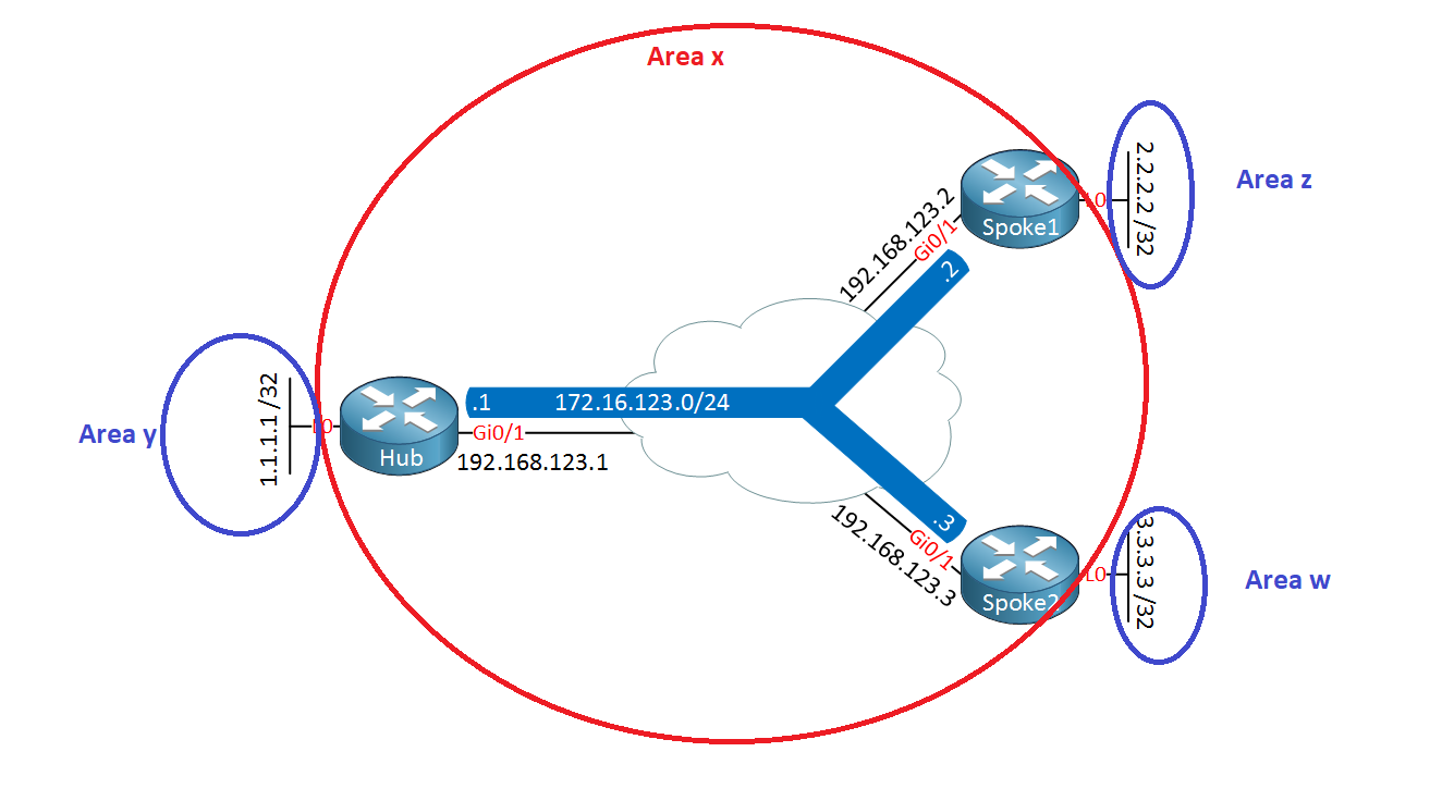
This way, we can have the hub and the spokes perform inter-area summarization instead.
Kind regards,
David
Hello David
In the lesson, Rene has set up all routers and all interfaces within Area 0. The only time he changed that is when he tried the stub area option and put everything in Area 1 except for L0 of the Hub, essentially making the whole DMVPN topology a stub.
The alternative you suggest is a good one. Essentially you are saying that the backbone area 0 is assigned only to tunnel interfaces on all devices, and non-backbone areas are assigned to interfaces facing networks behind spokes and hub. This way, the hub and all the spokes act as ABRs, so any topology changes behind them will not affect the other areas. This also allows summarization at the spokes. The only issue you should remember is that each spoke router will need to maintain LSDBs for both Area 0 and its local area. As DMVPN topologies get larger, this may put a strain on typically smaller routers that may be used for such spokes.
Ultimately, OSPF is fine for small DMVPN topologies, however, it is to be avoided for larger networks. Even with the arrangement you suggest, the SPF algorithm will eventually become too resource-intensive (memory, CPU, and bandwidth) in a DMVPN topology. For this reason, EIGRP and BGP are the preferred routing protocol for DMVPN deployments.
I hope this has been helpful!
Laz
Hello Laz!
Thank you very much for responding, everything is clear to me ![]() I have one more question, though. In the P2MP section of this lesson, I’ve noticed something strange.
I have one more question, though. In the P2MP section of this lesson, I’ve noticed something strange.
Why did the Hub router also learn about the spokes’ overlay IP addresses using OSPF? This also raises another question, why were the tunnel IP addresses advertised as /32 in the first place? This isn’t how OSPF works in other network types.
Thank you very much in advance.
David
Hello David
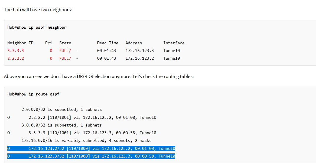
Indeed, intuitively, the spokes’ overlay IP addresses (aka tunnel interface addresses) should enter the routing table as directly connected since they’re on the same subnet, right? Not as OSPF-learned addresses. Well, this is due to the nature of point-to-multipoint network type.
When OSPF runs on a point-to-multipoint network, each router (including the hub) advertises its own tunnel interface IP address as a /32 route to other routers, even though the tunnel interfaces are configured on /24 subnets. Thus, the hub learns about the tunnel IP of each spoke as a /32 from OSPF, not as a directly connected route.
Now from OSPF’s point of view, those /32 addresses are no longer in the same subnet, therefore they are no longer considered directly connected, thus they must be learned via OSPF.
I think this also answers your second question concerning the /32 in the routing table on these particular routes.
I hope this has been helpful!
Laz
Hello Laz
Thank you for the explanation. I now understand that this is how it works in a P2MP network, but do we know the reason behind why it works like this? What’s the design reason behind having the routers advertise their tunnel IP addresses as /32?
David
Hello David
This behavior is due to the fact that OSPF views the point-to-multipoint topology as a series of point-to-point links. Since these links are point-to-point, then by definition, there can only be a single host on the other end of that link. Therefore, it saves time and resources to advertise these routes to neighbors using the most specific subnet possible which is /32, indicating a host route.
This behavior is more efficient, especially in topologies that use underlying point-to-multipoint technologies such as Frame-Relay and DMVPN (typically in hub and spoke topologies). This way, direct point-to-point communication with a particular spoke is more efficiently achieved, rather than sending traffic into a broadcast or pseudo-broadcast network segment.
I went in and labbed this up and tried to create a point to multipoint network type on an Ethernet link between two OSPF routers. I get the following in the routing table:
R2#show ip route
Codes: L - local, C - connected, S - static, R - RIP, M - mobile, B - BGP
       D - EIGRP, EX - EIGRP external, O - OSPF, IA - OSPF inter area
       N1 - OSPF NSSA external type 1, N2 - OSPF NSSA external type 2
       E1 - OSPF external type 1, E2 - OSPF external type 2
       i - IS-IS, su - IS-IS summary, L1 - IS-IS level-1, L2 - IS-IS level-2
       ia - IS-IS inter area, * - candidate default, U - per-user static route
       o - ODR, P - periodic downloaded static route, H - NHRP, l - LISP
       a - application route
       + - replicated route, % - next hop override, p - overrides from PfR

Gateway of last resort is not set

      1.0.0.0/32 is subnetted, 1 subnets
O        1.1.1.1 [110/2] via 192.168.12.1, 00:00:06, GigabitEthernet0/1
      2.0.0.0/32 is subnetted, 1 subnets
C        2.2.2.2 is directly connected, Loopback0
      192.168.12.0/24 is variably subnetted, 3 subnets, 2 masks
C        192.168.12.0/24 is directly connected, GigabitEthernet0/1
O        192.168.12.1/32
           [110/1] via 192.168.12.1, 00:00:06, GigabitEthernet0/1
L        192.168.12.2/32 is directly connected, GigabitEthernet0/1
Note that you get the directly connected network of 192.168.12.0/24, but you also get the OSPF-learned route of 192.168.12.1/32. Since the latter is more specific, any packets destined for 192.168.12.1 will use that routing entry while any other destination in the subnet will use the directly connected entry. The result is the same of course when using Ethernet, but it’s interesting how OSPF adds an extra route in this case.
(BTW, this should not be done in a production network. Ethernet links should use the default broadcast type for optimal operation with OSPF. I did this only for the purpose of understanding the behavior.)
I hope this has been helpful!
Laz
Hi,
For the phase 1 broadcast configuration, I’m confused as to how traffic is finding its way from one spoke to another.
Surely there needs to be NHRP mappings on the spokes to direct traffic to the hub for spoke-to-spoke communication:
Spoke 1
int tunnel 0
ip nhrp map  172.16.123.3 192.168.123.1
Spoke 2
int tunnel 0
ip nhrp map  172.16.123.2 192.168.123.1
Hello Samir
Your confusion is understandable. Remember that in a DMVPN topology, the role of NHRP and the routing protocol are separate and distinct.
- NHRP is used to resolve the next hop.
- Routing protocols are used to put destination networks in the routing table.
In a DMVPN phase 1 topology, by defintion, all traffic must traverse the hub. NHRP does not need a mapping to the spokes to direct traffic to the hub for spoke to spoke communication. This is because routing takes care of this.
When Spoke 1 wants to reach the network behind spoke 2, it looks at the routing table first. In spoke 1, OSPF has placed a route to the 3.3.3.3 network via 172.16.123.3, which is the next hop IP of Spoke 2. That’s OSPF’s idea of what the next hop should be.
The router then uses NHRP to determine how to get to that next hop. NHRP resolves that next hop to that of the hub, as is the case for Phase 1. So traffic is sent to the hub.
So the routing takes care of the identification of the remote networks, while NHRP takes care of directing such traffic to the hub in a Phase 1 arragement.
I hope this has been helpful!
Laz
Hi Laz,
Thanks for getting back to me.
I think I understand how the NHRP mechanism works. It basically converts the overlay next hop IP to the underlay (NBMA) destination IP address for routing of GRE encapsulated traffic across the physical network.
What confused me was that there is no mapping configured on Spoke 1 for the overlay next hop IP of 172.16.123.3 (Spoke 2) to the underlay (NBMA) IP address 192.168.123.1 (the hub), nor is there the equivalent on Spoke 2 for Spoke 1 communication via the hub.
However, I did notice that the tunnel destination was hardcoded so maybe mappings are not needed at all. I created a lab to test this and removed the mappings from the configuration in the course:
Spoke 1:
Spoke1(config-if)#no ip nhrp map 172.16.123.1 192.168.123.1
Spoke 2:
Spoke2(config-if)#no ip nhrp map 172.16.123.1 192.168.123.1
Spoke 1:
interface Tunnel0
ip address 172.16.123.2 255.255.255.0
ip nhrp authentication DMVPN
ip nhrp map multicast 192.168.123.1
ip nhrp network-id 1
ip nhrp nhs 172.16.123.1
tunnel source GigabitEthernet0/1
tunnel destination 192.168.123.1
No mappings:
Spoke1#sh ip nhrp
Spoke1#
And as I suspected, the traceroute to from Spoke 1 to Spoke 2 still worked:
Spoke1#traceroute 172.16.123.3
Type escape sequence to abort.
Tracing the route to 172.16.123.3
VRF info: (vrf in name/id, vrf out name/id)
1 172.16.123.1 3 msec 5 msec 4 msec
2 172.16.123.3 7 msec 5 msec *
Spoke 2:
interface Tunnel0
ip address 172.16.123.3 255.255.255.0
ip nhrp authentication DMVPN
ip nhrp map multicast 192.168.123.1
ip nhrp network-id 1
ip nhrp nhs 172.16.123.1
tunnel source GigabitEthernet0/1
tunnel destination 192.168.123.1
No mappings:
Spoke2#sh ip nhrp
Spoke2#
Again, the traceroute from Spoke 2 to Spoke 1 still worked:
Spoke2#trace 172.16.123.2
Type escape sequence to abort.
Tracing the route to 172.16.123.2
VRF info: (vrf in name/id, vrf out name/id)
1 172.16.123.1 6 msec 4 msec 3 msec
2 172.16.123.2 12 msec 7 msec *
Basically, I have concluded that NHRP mappings are not needed if the tunnel destination is hardcoded, however, on the hub where destinations are dynamic, NHRP is still required to resolve the overlay IP to an (NBMA) underlay IP address:
Hub#sh ip nhrp
172.16.123.2/32 via 172.16.123.2
Tunnel0 created 00:35:18, expire 00:08:33
Type: dynamic, Flags: registered nhop
NBMA address: 192.168.123.2172.16.123.3/32 via 172.16.123.3
Tunnel0 created 00:22:51, expire 00:07:08
Type: dynamic, Flags: registered used nhop
NBMA address: 192.168.123.3
Please correct me if I am wrong, but that is my understanding.
Thanks for the assistance.
Sam
Hello Sam
I think your experiment hits the nail right on the head! Yes, that is correct. Spokes don’t need the mappings since they use the hub to resolve the next hop IP, however, the hub needs mappings because the routing is dynamic. Thanks for sharing your experiment, it is a useful way to visualize and confirm this behavior.
I hope this has been helpful!
Laz
1 Like
Hello everyone,
if you try to replicate the 1.2.3. section (Non-Broadcast) make sure to add the following commands.
If you see an error like this follow along:
Neighbor ID     Pri   State           Dead Time   Address         Interface
N/A               0   ATTEMPT/DROTHER 00:01:13    172.16.123.1    Tunnel0
On the hub:
 ip ospf network non-broadcast
 ip ospf priority 255

router ospf 1
neighbor <Spoke 1/2 IP>
On the spokes:
 ip ospf network non-broadcast
 ip ospf priority 0

router ospf 1
neighbor <Hub-IP>
This is very important, otherwise your neighborships won’t come up.
I hope this is helpful to you.
Hello Thomas
Indeed you are correct. In order to correctly configure the non-broadcast OSPF network type on the specific setup, you must include the ip ospf network non-broadcast command on the interfaces on both the hub and the spokes. In the lesson, Rene has already set the priority of the spokes to 0 so they will never become DRs or BDRs, and that is enough to ensure that. The ip ospf priority 255 command is not strictly needed.
The error that you shared in your post shows that the OSPF neighbor state is stuck in ATTEMPT/DROTHER. The ATTEMPT state is a state that is specific to NBMA networks. It means that the OSPF process is trying to establish a neighbor relationship with a router that it has been configured to statically attempt to contact. A prolonged such state means that something is not quite right.
This is an expected error if you have a broadcast network (which is the default) along with statically defined neighbors. Such a config may result in duplicate efforts which interfere with each other. With a broadcast network type, OSPF will still attempt to dynamically discover neighbors using multicast hellos, while also trying to establish a neighbor relationship through unicast hellos to the static neighbors. This can cause the error you see in the OSPF neighbor table.
I will let Rene know to make any corrections necessary to the lesson.
I hope this has been helpful!
Laz
1 Like
Hello Rene, Thank u for sharing this knwoledge. Can u clarify to me why we don’t need for a DR/BDR election in DMVPN Phase 1 using OSPF as a routing protoocl ? I mean if there is a DR/BDR election what will bad happened ?
Hello Abderrahmane
Remember that a DR/BDR election occurs on a multi-access topology like Ethernet. When you have point-to-point topologies like DMVPN, the DR/BDR election can affect how OSPF will function. The point of avoiding an election is to ensure that the hub becomes the DR. If an election does take place, a spoke may inadvertently be elected as the DR, and that would cause problems in OSPF’s operation.
All spoke-to-spoke traffic traverses the hub router. Spokes do not establish direct tunnels with each other. For this reason, the hub’s tunnel interface acts as a central point for OSPF adjacency formation, making it the de facto DR by default. For stability, OSPF is typically configured with broadcast network type on the hub and spokes. However, spokes set ip ospf priority 0 to ensure they never participate in DR/BDR election. If they do, they may become the DR. The hub is explicitly configured to act as the DR (with higher priority), while spokes remain DROTHER (non-DR/BDR routers).
If a spoke did become the DR in this topology, this would break the OSPF operation because all OSPF routers must form an OSPF adjacency with the DR. But no spoke-to-spoke communication is possible, thus adjacencies would fail, and OSPF would not operate correctly. The only router that can create adjacencies will all other routers in the topology is the hub, and that is why it must explicitly be configured as the DR. Does that make sense?
I hope this has been helpful!
Laz