This topic is to discuss the following lesson:
Is there any reason in a real world deployment you might not want to disable BW? It seems more deterministic to use just BW.
Hi William,
As Rene has mentioned in the lesson, Cisco by default has Bandwidth and delay enabled while load and reliability are disabled as they change dynamically and Cisco recommended us to not enable them.
So in other term, Cisco wanted to say keep BW and delay only active. In the real world, I don’t see any reason to disable BW & delay. In case you want to disable any of them then it is better to disable the delay and keep the bandwidth enabled because the delay is calculated based on the sum of delays in the path as per the below formula’s
Metric = bandwidth (slowest link) + delay (sum of delays)
Here a good lesson explaining EIGRP K Values for more information.
Hope I could answer your question
Hi William,
The calculation is sum of all the delays and the lowest bandwidth.
So if you only enable the bandwidth then essentially the path length is not taken into consideration.
Usually you would prefer a shortest path if all the bandwidths are the same.
Stuart
Hi, Rene.
I was reading and researching on Google about the K6, and they say it represents jittler and energy. Jittler makes sense, but energy can’t understand. Are you going to use electricity as a metric? LOL
Would you know clearly how to explain the real need of K6 and how the metric is calculated?
Hi Stefanio,
As weird as it sounds, that’s exactly what they intend with energy yes ![]()
Here’s an excerpt from RFC 7868:
5.5.4.2. Energy
Use of Energy-based Path Selection results in paths with the lowest
energy usage being selected in a loop-free and deterministic manner.
The amount of energy used is accumulative and has results in a higher
aggregate metric than those having lower energy.Presently, EIGRP does not report energy usage, and as such the
default value will be zero (0).
On the Cisco site, you can find this:
likewise energy would be expressed in power per kilobytes per second of usage
So the idea is to select an interface, based on how much power it consumes.
You can find the wide metrics formula (that includes K6) here:
Hope this helps!
Rene
Hello,
I am going to use the below topology as a reference for my question.
I am trying to manipulate EIGRP path by changing the interface delay on ROUTER-1.
By default, this is how everything looks like.
Then I increased the interface delay and now the prefix is showing up as
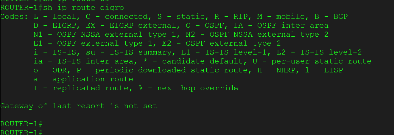
FD is Infinity in the EIGRP topology table and the prefix is not in the routing table anymore. Additionally, I am not running any other routing protocol and don’t have any static route either. Please shed some light on it.
Thank you so much in advance.
Best Regards,
Azm Uddin
Hello AZM
Usually, this happens when there is another routing protocol (or a static route) that provides a route to the destination in question with a smaller Administrative Distance (AD). But since you have already stated that you don’t have any of those, and the fact that the routing table is empty, indicates that the problem is elsewhere.
Now the FD will be infinity if the EIGRP metric is maxed out. Let’s do a calculation.
The EIGRP metric is a 32 bit value, which means it’s maximum value is 4,294,967,295. If you look at the EIGRP equation, taking into account only K1 and K3, you get the following:
Metric = 256 * [(10,000,000/bandwidth)+delay]
where bandwidth is in kilobits and delay is in tens of microseconds.
Looking at your configuration, I wasn’t able to see the speed of the link between the routers, but I did see that we are looking at an Ethernet port (not fast or giga), so I’m assuming 10 Mbps. So:
bandwidth = 10,000 kbps
delay ethernet = 1,677,721 tens of microseconds
delay loopback = 500 tens of microseconds
Plugging this into the equation, we get:
metric = 256 * [(10,000,000/10,000)+(1,677,721+500)] = 429,880,576
This is indeed smaller than the maximum of 4,294,967,295 and should not result in a maximum
However, looking at the FD of the route before you changed the delay, we see a composite metric of 131153920 but I calculate, based on the vector metrics, a metric of 512256. Also, I see a reported metric of 163840 to the loopback destination, whereas it should be 128320.
Again, in your output after the change in delay, I see that the composite metric is greater than the maximum EIGRP metric, although this calculation is not “correct” according to the equation.
The only thing I can think of is to check that the other K values are indeed 0 and that the delay and other parameters of the loopback interface have not been changed in some way. Check the default values of these parameters for the loopback to see if the specific router and IOS combination have some other defaults.
The discrepancy in the calculations must be due to a parameter that has not been included in our calculations of EIGRP. Can you take a look and let us know your findings?
I hope this has been helpful!
Laz
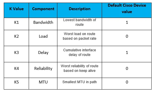
Please can you add something as a reference for the K values like this table below so their is no confusion as to which K value is for which property.
Very few webpages on the Internet actually tell you which K value is for which property.
Hello Matthew
I’ll relay your suggestion to Rene. Thanks for the feedback, it’s always helpful!
Laz
If I want to alter the delay on a connection using the EIGRP calcualtion (formula), how would I do that and where would I see the Metric result in the router?
Hello Marc
The delay metric is a value that is configured on the interface of a router. The following output shows the default values configured for this:
Router#show interface gigabitethernet 0/0
GigabitEthernet0/0 is administratively down, line protocol is down
  Hardware is iGbE, address is 5e00.0000.0000 (bia 5e00.0000.0000)
  MTU 1500 bytes, BW 1000000 Kbit/sec, DLY 10 usec,
     reliability 238/255, txload 1/255, rxload 1/255
  Encapsulation ARPA, loopback not set
  Keepalive set (10 sec)

  ! <--output omitted-->
Notice the value of BW and DLY. These are the values used to measure the bandwidth component and the delay component of the EIGRP metric. You can also see the reliability and the load on the very next line.
For the delay component, this is the value on a specific interface. The delay is measured as the total cumulative delay over all the traveresed interfaces to get to a particular destination. The delay is simply a value that is statically assigned to the interface. You can change it using the following commands:
Router#configure terminal
Enter configuration commands, one per line.  End with CNTL/Z.
Router(config)#interface gigabitethernet 0/0
Router(config-if)#delay 500
Router(config-if)#exit
Router(config)#exit
Router#
The result is that the delay has been changed:
Router#show interface gigabitethernet 0/0
GigabitEthernet0/0 is administratively down, line protocol is down
  Hardware is iGbE, address is 5e00.0000.0000 (bia 5e00.0000.0000)
  MTU 1500 bytes, BW 1000000 Kbit/sec, DLY 5000 usec,
     reliability 238/255, txload 1/255, rxload 1/255
  Encapsulation ARPA, loopback not set
  Keepalive set (10 sec)

  ! <--output omitted-->
It is now 5000 usec. Keep in mind that the command is applied in milliseconds but the output is shown in μs or microseconds.
Once you change this value, if you take a look at the EIGRP routing table, you will see a change in the EIGRP metric of any prefix using that interface as part of the path to get to the destination.
I hope this has been helpful!
Laz
Makes a lot more sense. thanks laz!
Hello Mr Rene
thank you for this course but I have a concern, what relationship exists between the variance for the load balancing , the K values for the metric and the transmission medium, indeed I am a bit confused when you mention that we can modify the bandwidth of a link to influence the best path and also we can change the K values including bandwidth and delay for the same, be a bit clear in this explanation, in what circumstances to use the k values and in what circumstances variance and bandwidth alone. I hope my question is well put
Hello Charles
The metric that is calculated for each possible path to a particular destination network using EIGRP is determined using the EIGRP formula as described in this lesson. That formula is based on the bandwidth, load, delay, and reliability of the links along the path. These are represented by K values 1 through 4. (K5 is actually not used as part of the best route calculation, but that’s a different story).
Now the question is, where does EIGRP get the information about these four characteristics? These values are all maintained on a per-interface basis on all the interfaces that are traversed along the path to the intended destination. Take a look at the example output of the show interfaces command below:
Router#show interfaces fastEthernet 0/0
FastEthernet0/0 is up, line protocol is up
  Hardware is AmdFE, address is cc02.58a9.0000 (bia cc02.58a9.0000)
  Internet address is 192.168.12.1/24
  MTU 1500 bytes, BW 100000 Kbit, DLY 100 usec,
     reliability 255/255, txload 1/255, rxload 1/255
Here you can see the following values:
- Bandwidth, labeled BW is at 100000 Kbit
- Delay, labeled DLY is 100 microseconds
- Reliability is at 255/255
- Load is shown as txload and rxload each at 1/255
Now, the bandwidth and delay are actually values that you can manually change. They’re labels that are assigned particular values by default based on the type of interface. For example:
- a 10Mbps link will have a BW of 10000 Kbit and a DLY of 1000 usec
- a 100Mbps link will have a BW of 100000 Kbit and a DLY of 100 usec
- a 1Gbps link will have a BW of 1000000 Kbit and a DLY of 10 usec
But you can go in and change these values manually. It doesn’t change the actual bandwidth of the interface, but it does affect the metric that is calculated by EIGRP and other routing protocols for traffic that traverses this interface.
Now reliability and load are calculated based on the actual number of errors detected on the interface and on the actual traffic on the link, respectively. These values are updated every 5 minutes. More info on all of these can be found in the following lesson:
So you see, you can affect the metric that EIGRP calculates by changing the bandwidth and delay values of the interfaces along the path to the intended destination. Now, what effect does that have on the variance for load balancing? It doesn’t affect the variance directly, but it will affect the metric measured for a particular path. That can change whether a particular path is considered part of the load-balancing arrangement or not depending upon the value of the variance. Does that make sense?
I hope this has been helpful!
Laz
very well explained thank you


