Hello guys,
to be honest, this is first time, I see someone interested in checksum/crc, since I finished my masters degree on computer university. It is cool to revive these old good times.
I want to add my 2 cents and clear the terms used in this thread: Parity vs Checksum vs CRC
I would not put my hand into fire for it, but there is what I rember.
Parity.
We have two types of parity:
Parity is just 1 bit value, thus it can be 0 or 1 in binary. Imagine we want to use parity checking for certain data, all data can be represented by using binary system of zeros and ones.
In case we are using even parity for verification the value of parity bit is equal to complement of total bits set to 1 in data, to make it even number.
So “Parity bit value” + “Number of bits set to 1 in data” = “even number”.
Example:
data value   even parity bit value
1111 1010    0
1011 1010    1
In case of odd parity the odd parity bit value is equal to complement of total bits set to 1 in data, to make it odd number.
So “Parity bit value” + “Number of bits set to 1 in data” = “odd number”.
Example:
data value   odd parity bit value
0110 0100    0
0110 0101    1
Parity error checking is pretty weak and it has no error correction ability. Its able to detect errors only in case just even number of bits in data were changed and all changes were made on different bits.
Example using even parity bit check:
data send /                          data received
parity bit    error 1     error 2    / parity bit
0001/1        0101/1      0111/1     0111/1
In this example received data of 0111/1 is passing even parity check, however originally it was 0001/1. Parity check failed to discover an error.
If parity check fails, we know that received data are corrupted, but we dont know which bit, how many bits were changed or position of changed bits. Thus Prity check does not have self-correction ability on receiving side.
Remember: Parity is based on adding complement of binary 0 or 1 to input data to make total number of binary ones even/odd (depends what parity you want).
Checksum.
This is shortcut of Check Summary. There are more bits involved for summary check, parity check has always 1 bit, summary check has more bits. Imagine IP header, there is 16 bit long Checksum field, means that it is 16bit-Checksum. Because checksum field is 16 bit long thats why total size of IP header (+ IP header options) has to be padded to multiply of 16 bits and thats why there are only allowed 32 bit increments in IP header + Options, its comming from 16bit field reserved for Checksum (this is just a guess).
Checksum is easily computed by writting X-bits on lines under each other and processing binnary addition, lines are X-bits long, representing X-bit Checksum.
To contrast this with in IP header, you have to write 16 bit long lines in binary
(in binary, 16 bits total) Version IHL ToS
(in binary, 16 bits total) TotalLength
(in binary, 16 bits total) Indentification
(in binary, 16 bits total) FragmentFlags FragmentOffset
...and so on (each line = 16 bits, because checksum field has 16 bits)
When you are calculating Checksum of IP header, the value of Checksum field is inserted as all zeros, or ignored and not taken into account at all (which is same as adding all zeros).
Checksum can discover more errors then Parity check, but not all of them, problem is when 2 errors are on same position in X-bit long lines, but on different lines.
Example with 8bit-Checksum for 16bit of binary data [0011 0001 0101 0010]:
#         original      received
line 1    0011 0001     0011 0000
line 2    0101 0010     0101 0011
---------------------------------
checksum  1000 0011     1000 0011
As you can see, checksum is same here, means this is going to pass the binary Checksum, howewer original and received data do not match (last bits on lines), therefore Checksum was useless to discover our two errors.
Checksum is better then Parity check for error discovery, because it uses more bits, but its not even close to 100 percent accuracy.
If Checksum detects error in received data, it has no ability to repair them, simply because it cannot detect on what line error occured. It can detect bit position of error bit, but cannot identify on what line it happened.
When you are adding binary strings and you have some carry bits on left side, you simply wite them on another line and add this line to current result.
Remember: Checksum is based on binary addition of equal long binary strings, resulting in same long result.
CRC.
On the other hand CRC generating algorithms are pretty badass. Used in many computer sciences, including networking, you have pointed Ethernet frame as nice example.
FCS is 32 bit long, means Ethernet use polynomial of 32nd degree. I dont know exactly which polynomial is used, but it can vary based on Ethernet standard anyway, for sure it can be found in documentation.
Polynomial of the 32nd degree is represented by 33 binary numbers (32 + 1, because we start with bit value on power of zero, same as when we are converting binary value to decimal, least sighnificant bit is Value to Power of zero and we need 33th bit, from right, that represents value on power of 32).
Lets ilustrate this on example. Polynomial of 6th degree is written by 7 (=6+1) binary numbers.
 binary number represents polynomial
 1011001                   1*x^6 + 0*x^5 + 1*x^4 + 1*x^3 + 0*x^2 + 0*x^1 + 1*x^0
                          which equals to polynomial
                           1*x^6 + 1*x^4 + 1*x^3 + 1*x^0
Dividing by 32nd degree polynomial results in 32 bits of remain, any additinal bit in remain would cause cycle, meaning it can be divided by 33 bit number again. Hence the word Cyclic in name.
This may be hard to understand from my poor English, I will try to rephrase.
To produce 32bit long CRC, you have to use 33 bits long divider (in binary) which represents polynomial of 32nd degree and garants us maximum of 32bits long remain.
The actual value that is put into FCS of Ethernet frame is 32bit CRC value = the remain after you divide input data polynomial with divider polynmonial used in certain Ethernet standard.
This is important definition, CRC = remain after polynomial division. Important keyword is REMAIN.
Computers work with binary system and when they want to divide two polynomials (that can be written in binary) they have to perform retract binary operation, usually we are retracting multiple times, until dividend is lower then divisor, when divisor is higher then dividend then we stop and what is actual value of dividend is our remain. When we are perfoming binary retraction sometimes we have to carry some bits to get the integer part of result correct, but now look at CRC definition again, it says we need only REMAIN after division. To get only remain we use so called modulus operation, which is giving us only remain.
This is example what is modulus 4 about in decadic system.
16 / 4 = 4, where 4 is integer part and remain is 16 - 4 * 4 = 0, thus modulus = 0
17 / 4 = 4, where 4 is integer part and remain is 17 - 4 * 4 = 1, thus modulus = 1
18 / 4 = 4, where 4 is integer part and remain is 18 - 4 * 4 = 2, thus modulus = 2
19 / 4 = 4, where 4 is integer part and remain is 19 - 4 * 4 = 3, thus modulus = 3
So far we have modulus equal to 3, because we are counting modulus of 4, next number gives us again modulus equal to 0, thus this is ONE modulus Cycle.
Next number is starting another modulus Cycle… this is reference to word Cyclic in CRC.
20 / 4 = 5, where 5 is integer part and remain is 16 - 4 * 4 = 0, thus modulus = 0
As you guys pointed in previous posts in this thread dividing polynomials can be time consuming, not like its hard, just time consuming so its not the thing you wanna do on paper. But CRC requires only remain after division and modulus operation is giving us this remain. Now is the important part and the place where beauty of algebra really kicks in. When we want to compute only remain after retracting two binary numbers we can use XOR operation, XOR is very similar to binary retraction, but it ignores any carried bits (because these bits belong to integer part of result after division), it will be more visible from example. XOR is basically equal of doing modulo 2 operation (the number 2 because we use binary numbers 0 and 1 in remain. As you can see in upper example we used modulo 4 that always produces numbers 0,1,2 or 3).
Because we basically dont care what is the exact full result of polynomial division (interger part is cycled out, whatever it is and does not matter how many XOR cycles it takes) but we care only for remain after this division to put it into FCS field.
We can use mentioned XOR trick.
XOR results for two binary values:
1 xor 1 = 0
0 xor 0 = 0
1 xor 0 = 1
0 xor 1 = 1
As we can see result of XOR of binary numbers is always binary 1 or binary 0, thus ist modulus of 2, because every higher number would start a new cycle.
Thus lets try to XOR two binary numbers.
#1        1010 1100
#2        0110 0101
      xor =========
result    1100 1001
Now to the example how to compute CRC. Lets say we want to transmit these bits [0111 0110 1001 11] and use generating polynomial of 11 1101 (which is 1x^5 + 1x^4 + 1x^3 + 1x^2 + 0x^1 + 1x^0, degree is 5). Every polynomial that we are using as divider is called Generating Polynomial, I will use shortcut “GP” from now on. In Ethernet standards are these GPs defined, so both, sender and also receiver know what GP to use.
Because we are using GP of 5th degree we add exactly 5 zeroes to the initial transmit bits, these 5 added bits will lately carry 5bit CRC.
Thus we start with the following
input string         : 0111 0110 1001 11
GP                   : 1111 01
input + bits for CRC : 0111 0110 1001 1100 000


   0111 0110 1001 1100 000  <-- input + 5 bits for CRC represented by 5 zeroes
    111 101                 <-- GP, shifted to first occurance of 1 in upper line
xor=======================
   0000 1100 1001 1100 000  <-- result, remainder after first XOR cycle, at
                                positions where GP is not defined simply write
                                same number what is on upper line

   0000 1100 1001 1100 000  <-- result of previous XOR cycle
        1111 01             <-- notice that GP got shifted to first 1 in upper line
xor=======================
   0000 0011 1101 1100 000  <-- result of second XOR cycle, each XOR cycle
                                represents one rectraction  of GP from dividend,
                                no bits are being carried to the left

   0000 0011 1101 1100 000  <-- result of second XOR cycle
          11 1101           <-- GP got shifted by 2 bits, to first 1 in upper line
xor=======================
   0000 0000 0000 1100 000  <-- result of third XOR cycle, because remain
                                is now 1100 000, which is higher then our GP
                                of 111 101, we continue to XOR

   0000 0000 0000 1100 000  <-- result of third XOR cycle
                  1111 01
xor=======================
   0000 0000 0000 0011 010  <-- result of 4th XOR cycle, remain is now 11 010,
                                which is lower then our GP of 111 101 thus we
                                finished the calculation, 11010 is 5bit-CRC

Our results.
input binary string : 0111 0110 1001 11.. ...
calculated CRC      : .... .... .... ..11 010
what we gonna xmit  : 0111 0110 1001 1111 010
Just append crc to the input message.
Now you see that mechanism for calculating CRC value is pretty easy.
CRC verification.
Lets say receiving side got the data without errors and received 0111 0110 1001 1111 010, as it knows GP, because it is standard, it can XOR the receveid imput with GP.
   0111 0110 1001 1111 010
    111 101
xor=======================
   0000 1100 1001 1111 010

   0000 1100 1001 1111 010
        1111 01
xor=======================
   0000 0011 1101 1111 010

   0000 0011 1101 1111 010
          11 1101
xor=======================
   0000 0000 0000 1111 010

   0000 0000 0000 1111 010
                  1111 01
xor=======================
   0000 0000 0000 0000 000  <-- result is all zeros, means we
                                received data without errors
What in case receiving side gets the data and error occured in transmission?
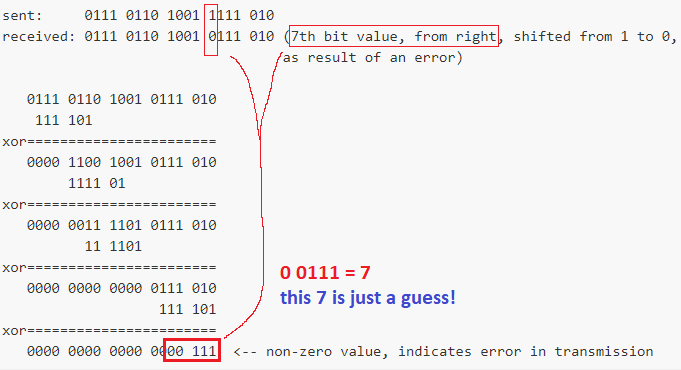
sent:     0111 0110 1001 1111 010
received: 0111 0110 1001 0111 010 (7th bit value, from right, shifted from 1 to 0,
                                  as result of an error)

   0111 0110 1001 0111 010
    111 101
xor=======================
   0000 1100 1001 0111 010
        1111 01
xor=======================
   0000 0011 1101 0111 010
          11 1101
xor=======================
   0000 0000 0000 0111 010
                   111 101
xor=======================
   0000 0000 0000 0000 111  <-- non-zero value, indicates error in transmission
If you look at it closely, in every XOR cycle you retract value of GP.
This works because:
- multiplication is based on addition, 3x5=15 which is same as 0+5+5+5=15, we have to add 5 exactly 3 times to number 0 to get number 15.
- division is based on retraction, 15/3=5 which is same as 15-3-3-3-3-3=0, we have to retract 3 exactly 5 times from 15 to get number 0.
- however this introduces another problem, 15/0=undefined, because division by 0 in only defined in complex numbers and computers use binary numbers, they cant divide by zero (how many times you have to retract 0 from 15 to get zero?).
To compare Checksum with CRC, the Checksum is obtained using additive operations meanwhile CRC is obtained using retractive operation.
CRC is very good for detecting errors, on top of it when we combine it with Hamming codes (what do Parity for blocks of input) we can achieve self-correction of errors on receiving side. However this is not the case of Ethernet, it drops frames that fail CRC.
Another advantage of CRC vs Checksum is that for Checksum you need all the data (or at least entire block) to calculate it, but CRC can be calculated on-the-fly as you are receiving data, thus when you are receiving Ethernet frame, after SFD first comes in destination MAC, when you have fist bit that is equal to 1 in this MAC you can snap GP to it, then wait for following 32 bits after this first bit, when they arrive we can start calculating CRC value.