First of all, the static routing command does not include the word “static” as you have it in your post. I assume this was a typo, so I’ll assume that you mean the commands without this.
When a router makes a routing decision, what it needs to know to do it depends on the technology being used. For Ethernet, it must know two things: the next hop IP address, and the exit interface. For serial connections (point to point) it only needs to know the exit interface. This is because there can only be a single device on the other end of a serial link.
For this reason, static routing can be applied in various ways, and you show them in your post. Let me go through them one at a time.
ip route 10.1.1.0 255.255.255.0 192.168.1.1
This command will tell a router that any destination IP in the network 10.1.1.0/24 should be sent to the next hop IP of 192.168.1.1. This entry alone however, is not enough to allow a packet to be routed correctly. Where is 192.168.1.1? A second routing table lookup must be made for 192.168.1.1 in order to determine the exit interface for the next hop IP. This is called a recursive routing table lookup. It is assumed that the 192.168.1.1 address is on a router that is directly connected, so a “directly connected” entry that shows an exit interface should appear in the routing table. If not, routing will fail, because the next hop IP cannot be found.
ip route 10.1.1.0 255.255.255.0 fa0/0
This command tells us the exit interface, but does not tell us the next hop IP. For Ethernet, both pieces of information are necessary. If this router receives a packet with a destination IP of 10.1.1.5 for example, it will know to send it out of fa0/0, but it doesn’t know to which next hop IP. Remember, this Ethernet segment may have many hosts connected to it. What the router will do is it will begin sending ARP requests for the 10.1.1.5 IP address. The routing will be successful ONLY IF this destination host is directly connected to the fa0/0 interface. Otherwise, routing will fail.
ip route 10.1.1.0 255.255.255.0 S0/0
Because serial links are by definition point to point, it is assumed that the next hop is the device on the opposite end of the link. For this reason, this command will function correctly, as packets sent to 10.1.1.5 for example, will be sent out the interface, and will be processed by the device on the other end of the link.
ip route 10.1.1.0 255.255.255.0 fa0/0 192.168.1.1
This command will eliminate a recursive lookup in the IP routing table. Remember that Ethernet requires both the exit interface, and the next hop IP address to successfully route the packet. Here both pieces of information are included in one routing table entry, so no recursive lookup will take place. Routing will be successfully achieved with only a single routing table lookup.
ip route 10.1.1.0 255.255.255.0 S0/0 192.168.1.1
This command will also work, but it carries redundant information. It has both an exit serial interface, and a next hop IP address. Even without the next hop IP address, this command will work, since serial connections don’t require the next hop IP.
Strictly speaking IPv4 doesn’t allow you to use a /30 subnet, since this would only give you two IP addresses, the network, and the broadcast, which can’t be used for hosts. The smallest network you can practically use is a /30 with a network, a broadcast, and two host addresses for a total of four.
However, Cisco and other vendors allow the use of a /31 address space for point to point connections, even if you are using Ethernet. You can connect two routers together using 10.10.10.0/31 and 10.10.10.1/31 for example, and it will work correctly. This has been enabled on networking devices in order to make a more efficient use of the IPv4 address space. It is not strictly supported by the official definition of IPv4, but it is supported by many vendors as an “exception”.
It is really a very nice explanation. But for more clarity can I request you a pictorial representation of ip route 10.1.1.0 255.255.255.0 with one example.
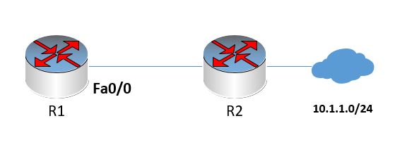
All pictorial representations for all of the above scenarios will actually look the same: one router connected to the next, where the exit interface will either be Fa0/0 or S0/0. For example, for the ip route 10.1.1.0 255.255.255.0 fa0/0 command, we would have:
where the command is implemented on R1. The result will be that any packet destined for 10.1.1.X will be sent out of Fa0/0. But before it is sent out, R1 will send an ARP request out of Fa0/0 for the destination IP address. If R2 has proxy ARP enabled, it will respond with its own MAC address, and R1 will encapsulate the packet into a frame with the appropriate destination MAC and will be sent to R2. R2 will then forward the packet to the destination network.
Each of the other scenarios will use similar diagrams.