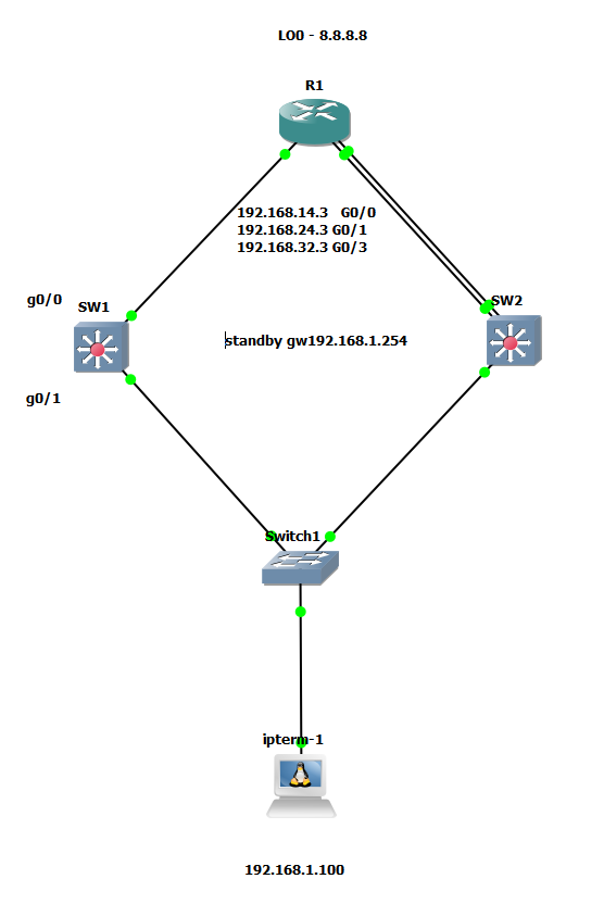
Hi. What if SW2 was AVG? What I am trying to achieve is: If both links fails the SW1 should be AVG. I tried to simulate this with preempt option but no success. Please see my config:
SW1:
Keep in mind that an AVG and an AVF are two different things. The priority value configured will determine which switch will become AVG, but the weighting values will determine if a particular switch will be an AVF. Remember there is only one AVG, while all functioning switches in the group are AVFs.
Now in your scenario above, SW2 will be AVG. Even if both links to the router fail, it will still remain AVG. This is because even if both links fail, SW2 and SW1 still maintain a connection between them via the 192.168.1.0/24 subnet, so there is no reason why SW2 cannot continue to function as AVG. Remember, the AVG is responsible for answering Address Resolution Protocol (ARP) requests for the virtual IP address. Load sharing is achieved by the AVG replying to the ARP requests with different virtual MAC addresses. SW2 can continue to do this even if both its links fail.
If the currently active AVG fails in this function, only then will the backup AVG take over.
Round-robin: the AVG will hand out the virtual MAC address of AVF1, then AVF2, AVF3 and gets back to AVF1 etc.
Host-dependent: A host will be able to use the same virtual MAC address of an AVF as long as it is reachable.
Weighted: If you want some AVFs to forward more traffic than others you can assign them a different weight.
I’m not sure to understand the difference between glbp priority and glbp weighting.
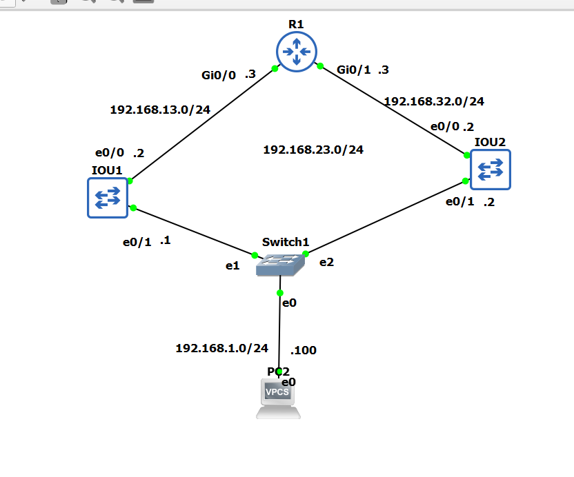
Also I’ve tried to replicate this lab but I think that a routing loop is occurring during pinging the loopback of R1.
The glbp priority parameter affects which device will become the AVG. Remember there is only one AVG and it is the device that assigns the virtual MAC address to all other devices running GLBP. Priority has nothing to do with which how data traffic will be forwarded.
The glbp weighting parameter on the other hands, is used to determine if a device will become an AVF. Remember there are multiple AVFs in a GLBP group, and an AVF is simply a device that will forward traffic. So weighting ultimately affects the number of available devices through which traffic can be forwarded.
Concerning the wireshark captures that contain the frames designated with the “loop” protocol, this doesn’t necessarily mean that you have a loop in your topology.
The Loop protocol, more correctly referred to as the Ethernet Configuration Testing Protocol (CTP) is an obscure protocol that has been part of Ethernet since it’s inception by the DEC/Intel/Xerox consortium created the Ethernet v2.0 specification. It’s not even defined at all within any of the IEEE 802 specs. It is a protocol that can be considered as a layer two ping equivalent. Some more information about it can be found here:
It can be thought of as an Ethernet keeplaive message that can be used to detect loops. As you can see all loop frames have the same source and destination MAC addresses. It is used to detect self-looped ports. If a switchport receives a loop frame it sent to itself, it would be put in err-disabled state. It has been found however by some users that the loop protocol is actually ignored by some platforms while others still use it.
Now it is interesting that you see these frames in your ports. This gives me the impression that you have not configured the ports on the switches connected to the router as routed ports. So the “router facing” ports on the switches should be configured as routed ports (i.e. no switchport). This way no loop protocol frames will be seen on these ports. Also, do some troubleshooting with STP to see if there are any blocked ports to see if you actually do have any physical L2 loops. Based on the topology, there should be no ports blocked by STP.
Take a look at those aspects of the topology to continue your troubleshooting, and let us know if there are additional questions that come up.
Once again just like with VRRP, HSRP and GLBP any of you that are using GNS3 and happen to be having trouble getting the devices to talk to one another and become active/standby and it does not work despite having layer 3 connectivity and everything being configured correctly.
You need to use the global config command:
no ip igmp snooping
This needs to be on all switches the mutlicast traffic passes through
I had to do this on IOU L2 images, show version output here:
IOU1#show version
Cisco IOS Software, Solaris Software (I86BI_LINUXL2-IPBASEK9-M), Experimental Version 15.1(20130726:213425) [dstivers-july26-2013-team_track 105]
Copyright (c) 1986-2013 by Cisco Systems, Inc.
Compiled Fri 26-Jul-13 16:12 by dstivers
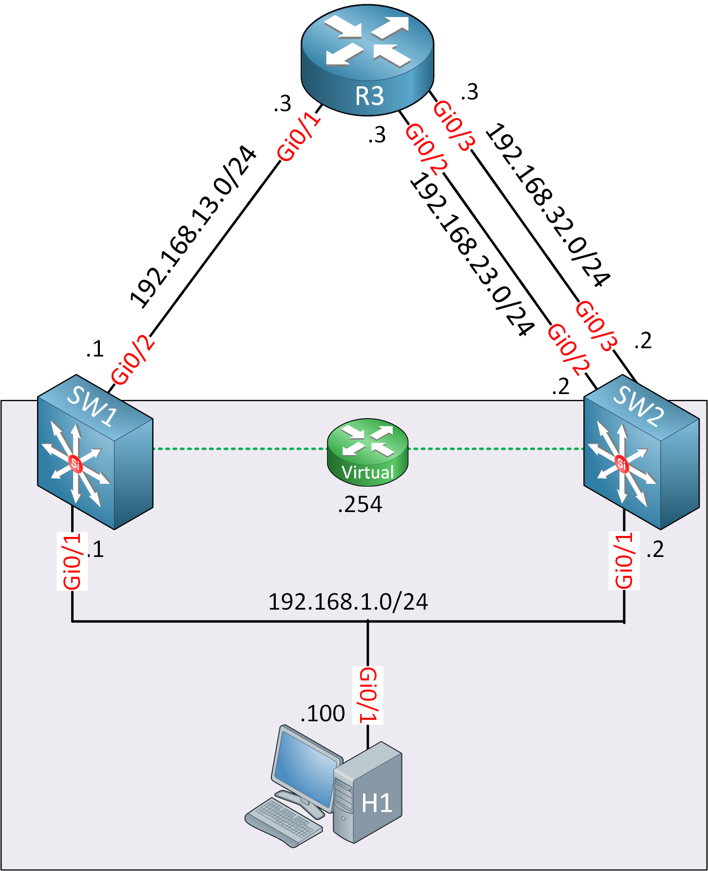
I don’t quite understand one part of your comment here: " SW2 will be AVG. Even if both links to the router fail, it will still remain AVG. This is because even if both links fail, SW2 and SW1 still maintain a connection between them via the 192.168.1.0/24 subnet, so there is no reason why SW2 cannot continue to function as AVG." Per Patryk’s configuration, if two links fail, then SW2 priority will be 120, which is lower than 150, why won’t SW1 be the AVG since it has higher priority now?
SW1 and SW2 can communicate with each other over their Gi0/1 interfaces in order to determine the AVG, and the AVF. Even if the links towards R3 fail, this link remains active.
The role of the AVF is affected directly by any failure in the uplinks to R3. If Gi0/2 goes down on SW1 for example, SW1 can no longer play the role of the AVF.
However, Unlike the AVF, the role of the AVG doesn’t require this link to R3 be active. So SW1 can remain the AVG, even if its Gi0/1 link goes down. The only failure that will cause another switch to take over the role of AVG is if the switch itself fails (power outage, corrupted IOS, the GLBP process fails) or if the Gi0/1 interface fails and communication with SW1 is lost.
Actually, if two links to the router fail, the AVG priority will not change. However, the weight which determines the AVF will change.
Q1) I want to know can we enabled tracking for AVG+AVF and AVF b/c just in case suppose AVG connectivity to R3 goes down means no more redundancy in a network?
Same question for VRRP and HSRP where we use concept of active and standby?
Q2) In GLBP tracking can only be enabled if we are having connectivity of AVF to R3 by
two links?
Reason for asking second question is b/c we are using here concept of lower and
upper threshold value , is single threshold can also be used ?
Tracking is a feature that is useful only for the AVF and not the AVG. The AVG is only responsible for assigning the virtual MAC to all the AVFs (including itself) and responding to the ARP requests of hosts for the gateway. All participating gateways will continually monitor each other’s availability, and if the AVG is no longer reachable by the other gateways, only then will the backup AVG take over. The AVG does not depend on the state of the interfaces. AVGs are chosen based on the configured priority.
The AVF on the other hand does depend on the state of the interfaces, and it is the AVF that can be affected by the tracking feature. The lesson describes this feature in full.
For VRRP and HSRP, take a look at there respective lessons.
It depends upon the resulting weight factor if one of those links goes down. The weighting as well as the lower and upper threshold values, are useful if you have multiple uplinks. If you have a single uplink, such as is the case with SW1, then the tracking will simply use the state of that uplink alone to determine the forwarding status. But the weighting gives you more control over which situations will cause a device to no longer be considered an AVF.
hello Mr. Rene and thank you for the course; I have a multi-part question that concerns me so much. I would like to know when we have to implement these different redundancy protocols mentioned below, do these protocols take effect only when the physical link is faulty? and what is the main difference of the use of these protocols for load balancing compared to the use of routing protocols (EIGRP; OSPF…). I apologize for questions that seem trivial
This is an excellent question. Gateway redundancy protocols such as GLBP and HSRP, are used to allow hosts on a subnet to have redundancy on their default gateway. These allow multiple gateways to share the same IP address used as the default gateway by the hosts. If one gateway goes down, the other is available to take over. More information can be found in this lesson:
Routing protocols, such as OSPF or EIGRP, can deliver redundancy as well, but not to hosts. Hosts don’t participate in routing protocols, they typically are configured with a single default gateway, and routing protocols will not change that. However, routing protocols do deliver redundancy within the network, and not at the gateway of particular hosts within a subnet.
So protocols like GLBP and HSRP and VRRP deliver redundancy to the default gateway of hosts while routing protocols can deliver redundancy within the infrastructure of a network.
Hello Dear,
thanks for this easy and smooth explanation!
I have same scenario, but the IP is encapsulated in a L2 vlan to pass it through my network to the customer but the challenge is that it will cause a L2 loop as I have to pass the vlan from both directions, what do you suggest as a work around for such scenario.
Great to hear that this was helpful. As for your question, it’s unclear what you are trying to achieve. Can you clarify what you want to be able to do and share with us a topology of your particular scenario so we can help you further?
interface GigabitEthernet0/0
 ip address 192.168.13.3 255.255.255.0
 duplex auto
 speed auto
 media-type rj45
!
interface GigabitEthernet0/1
 ip address 192.168.32.3 255.255.255.0
 duplex auto
 speed auto
 media-type rj45
!
interface GigabitEthernet0/2
 no ip address
 shutdown
 duplex auto
 speed auto
 media-type rj45
!
interface GigabitEthernet0/3
 no ip address
 shutdown
 duplex auto
 speed auto
 media-type rj45
!
ip forward-protocol nd
!
!
no ip http server
ip route 192.168.1.0 255.255.255.0 192.168.13.2
ip route 192.168.1.0 255.255.255.0 192.168.32.2
Switch1
version 15.2
service timestamps debug datetime msec
service timestamps log datetime msec
no service password-encryption
service compress-config
!
hostname IOU1
!
boot-start-marker
boot-end-marker
!
!
logging discriminator EXCESS severity drops 6 msg-body drops EXCESSCOLL
logging buffered 50000
logging console discriminator EXCESS
!
no aaa new-model
!
!
!
!
!
no ip icmp rate-limit unreachable
!
!
!
no ip domain-lookup
ip cef
no ipv6 cef
!
!
!
spanning-tree mode pvst
spanning-tree extend system-id
!
!
!
!
!
!
!
!
!
!
!
!
!
!
!
interface Ethernet0/0
 no switchport
 ip address 192.168.13.2 255.255.255.0
!
interface Ethernet0/1
!
interface Ethernet0/2
!
interface Ethernet0/3
!
interface Ethernet1/0
!
interface Ethernet1/1
!
interface Ethernet1/2
!
interface Ethernet1/3
!
interface Ethernet2/0
!
interface Ethernet2/1
!
interface Ethernet2/2
!
interface Ethernet2/3
!
interface Ethernet3/0
!
interface Ethernet3/1
!
interface Ethernet3/2
!
interface Ethernet3/3
!
interface Vlan1
 ip address 192.168.1.1 255.255.255.0
 glbp 1 ip 192.168.1.254
 glbp 1 priority 150
 glbp 1 preempt
 glbp 1 authentication md5 key-string kostas
!
ip forward-protocol nd
!
ip tcp synwait-time 5
ip http server
ip http secure-server
!
ip ssh server algorithm encryption aes128-ctr aes192-ctr aes256-ctr
ip ssh client algorithm encryption aes128-ctr aes192-ctr aes256-ctr
!
!
!
!
 --More--
Sw2
Current configuration : 1598 bytes
!
! Last configuration change at 21:42:30 UTC Tue Feb 21 2023
!
version 15.2
service timestamps debug datetime msec
service timestamps log datetime msec
no service password-encryption
service compress-config
!
hostname IOU2
!
boot-start-marker
boot-end-marker
!
!
logging discriminator EXCESS severity drops 6 msg-body drops EXCESSCOLL
logging buffered 50000
logging console discriminator EXCESS
!
no aaa new-model
!
!
!
!
!
no ip icmp rate-limit unreachable
!
!
!
no ip domain-lookup
ip cef
no ipv6 cef
!
!
!
spanning-tree mode pvst
spanning-tree extend system-id
!
!
!
!
!
!
!
!
!
!
!
!
!
!
!
interface Ethernet0/0
 no switchport
 ip address 192.168.32.2 255.255.255.0
!
interface Ethernet0/1
!
interface Ethernet0/2
!
interface Ethernet0/3
!
interface Ethernet1/0
!
interface Ethernet1/1
!
interface Ethernet1/2
!
interface Ethernet1/3
!
interface Ethernet2/0
!
interface Ethernet2/1
!
interface Ethernet2/2
!
interface Ethernet2/3
!
interface Ethernet3/0
!
interface Ethernet3/1
!
interface Ethernet3/2
!
interface Ethernet3/3
!
interface Vlan1
 ip address 192.168.1.2 255.255.255.0
 glbp 1 ip 192.168.1.254
 glbp 1 preempt
 glbp 1 authentication md5 key-string kostas
!
ip forward-protocol nd
!
ip tcp synwait-time 5
ip http server
ip http secure-server
!
ip ssh server algorithm encryption aes128-ctr aes192-ctr aes256-ctr
ip ssh client algorithm encryption aes128-ctr aes192-ctr aes256-ctr
!
!
!
!
!
control-plane
!
!
line con 0
 exec-timeout 0 0
 privilege level 15
 logging synchronous
line aux 0
 exec-timeout 0 0
 privilege level 15
 logging synchronous
line vty 0 4
 login
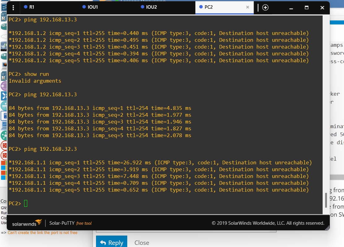
I am trying to ping from 192.168.1.100 host to Router via 192.168.13.3 or 192.168.32.3 and in case i am achieving from 13.3 i am not able from 32.3 and vice-versa. I am closing interfaces eth0/0 on SW1 or Sw2 interchangeable and i get the same results.
This is purely a routing issue. Notice that SW1 does not have a route to 192.168.32.0/24 and SW2 does not have a route to 192.168.13.0/24.
That means that when SW1 is active, and you ping 192.168.32.1, the ping reaches SW1, but SW1 has no route to the destination network, so it drops the packet. However, while SW1 is active, it does have a route to the 192.168.13.0/24 network since it is directly connected.
Now as soon as SW2 becomes the active switch, the opposite happens:
When SW2 is active, and you ping 192.168.13.1, the ping reaches SW2, but SW2 has no route to the destination network, so it drops the packet. However, while SW2 is active, it does have a route to the 192.168.32.0/24 network since it is directly connected.
As for both devices becoming active, this is typically due to the fact that they have lost connectivity between them. If a GLBP device has no connection to its pair, it will assume it has gone down and will become active. In such cases, troubleshoot the connectivity between the GLBP devices themselves, on the particular VLAN that the redundant SVIs are on.
Sorry but i will disagree! SW1 - Sw2 forms a group between as glbp, vrrp, hsrp.
Yes it getting confused with routing protocols and how FHRP works!!
When SW1 is active, Sw2 is backup the virtual ip is getting the ip-gateway of client.
So when i ping from host to internet SW1 as a master get the packets and either forward/routing them to the up stream. In case the SW1 is down , then SW2 is the master , Then SW2 collects the data since it hears to the same vip and forward/routing the packets to up devices.
If i configure SW1 or/and SW2 devices wth static routes to .23.0 or .32.0 networks then no FHRP is nneded to take place to the topology since i am the FHRP. For a dynamic protocol like FHRP the whole procedure should be happening automatically.
So , i searched the intentet and gns3 with classic IOU2, IOU3 devices does not work well, it has inconsistencies. Either u get expected results either not.
I am looking to wok on eve-ng for expirement and see the reactions.
One issue guys on gns3 is that no ip igmp snooping should be configured, although no results.
Finally take a look the following configuration running on bare metal ubuntu 22.10 machine:
1)hsrp works as expected , vrrp not soin case of vrrp:
![Screenshot from 2023-02-25 19-27-52|491x445]
(upload://cpcAYVQKxNsGZlzVE0CrYJjpSiW.png)
According to the following senario:
SW1 - active for group 1 , backup fro group 2
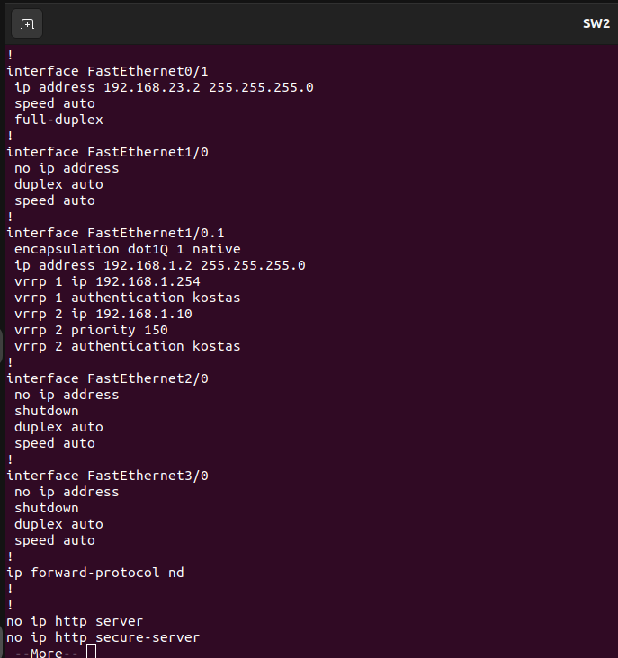
SW2 - backup fro group 2, active for group 1
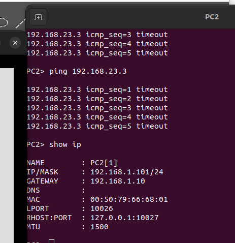
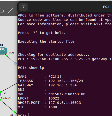
host 1 configured wth ip-gateway 1.254/24 from group 1
host 2 configured wth ip-gateway 1.10/24 from group 2
Performing load balancing and recovery.
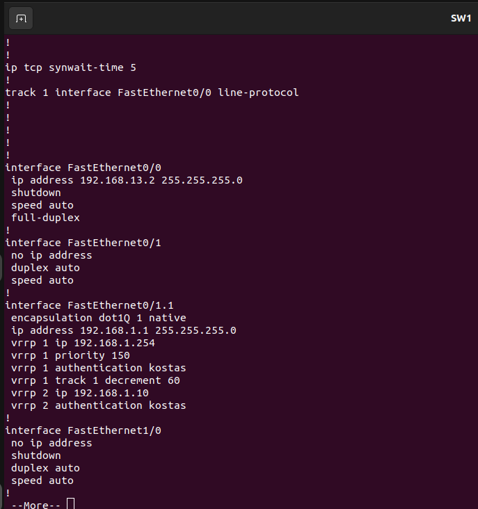
Load balancing works fine. Now SW1 f0/0 tracking line-protocol is down , SW2 becomes the active for group 1 , als is already active for group 2.
Host 1: ping 192.168.1.254 works, ping 192.168.23.3 works
Host 2: ping 192.168.1.10 works, ping 192.168.23.3 NOT WORKING.
So is there any case the double groups mastering to affect the functionality of one to another. ON HSRP , there is a case of redirection , the source- SW2 mac address should be the destination - mac - host- address, so if the mac addresses deffers there is a case the packets may or not dropped.
Can u explain me the above problem? Can u please repeat the procedure and verify that there is problems wth gns3 on FHRP protocols in order to not be confused more people inside here?
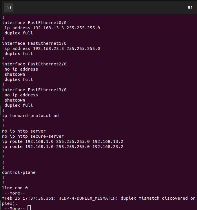
ip route 192.168.1.0 255.255.255.0 192.168.13.2
ip route 192.168.1.0 255.255.255.0 192.168.23.2
i have to add these:
ip route 192.168.1.0 255.255.255.0 192.168.1.254
ip route 192.168.1.0 255.255.255.0 192.168.1.254
ip route 192.168.1.254 255.255.255.0 192.168.13.2
ip route 192.168.1.254 255.255.255.0 192.168.23.2
Remember, the routing is there to route traffic upstream to R1. The FHRP is there only for the purpose of delivering a redundant gateway for the host. Any routing you create will not directly affect the FHRP functionality. Even when the routing protocol is configured, FHRP is still needed.
Remember, FHRP and routing are two distinct and separate processes. However, you must ensure that the routing works correctly as well to take advantage of the benefits of FHRP.
Hmm, I’m not sure that this is what solved your problem. You must keep in mind that in the first case, because you have two static routes with identical ADs, you will have load balancing. This is not ideal in an FHRP situation. In the second case, you are performing recursive routing, which is not ideal either, because it requires additional processes to determine the outgoing interface. However, the recursive routing seems to have canceled out the load balancing of the routing, resulting in a successful ping. Although it works, it can cause unpredictable results.
Take a look at this Cisco documentation for best practices that have to do with using FHRPs and routing together:
Can you help me to explain what is load sharing and load balancing , i am unable to differentiate , can you help me to understand with any topology if any reference you have
Can you advised what threshold value should be consider and how you decide it if both link is down between R1 and SW2 , what will be threshold value if there is only one link between SW1 and RA 1 and it goes down then it should not be an AVF but what threshold we need to consider ?