GLBP (Gateway Load Balancing Protocol)

Hello Shivam

Load balancing and load sharing two terms used generally in networking. They are often used interchangeably, but they do have slightly different meanings.

Load Balancing: This is a technique that distributes network traffic across multiple servers or paths to ensure no single server or path is overwhelmed. This can be done using various algorithms such as Round Robin, Least Connections, and IP Hash. The goal of load balancing is to optimize resource use, maximize throughput, minimize response time, and avoid overload of any single resource. Load balancing is usually done by a dedicated device, like a load balancer.

Load Sharing: This is similar to load balancing, but it doesn’t necessarily distribute traffic evenly. Instead, it allows you to manually or automatically allocate traffic based on current network conditions, capacity, or other factors. In load sharing, traffic is distributed among multiple paths based on the bandwidth of the links. If one link has more bandwidth, it can carry more traffic compared to a link with less bandwidth.

Both of these concepts can be applied to technologies such as EtherChannel, routing protocols such as OSPF, EIGRP, and BGP, or to FHRP technologies such as VRRP, HSRP, and GLBP.

Remember, these terms are often used loosely, so ultimately, the meaning and definition of these terms should be determined based on the context of their use.

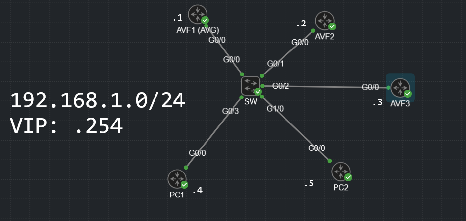
Now for the specific case of GLBP, the term Load Balancing is actually part of the protocol’s name, and in this context, it means evenly distributing the load that a default gateway would experience across two or more physical devices.

The threshold configuration has several components. First, you must determine how much of a decrement you will have for the failure of each link. In this particular case, Rene has configured a decrement of 20 for the weighting of each link, and this was done with the following configurations:

SW2(config)#track 2 interface GigabitEthernet 0/2 line-protocol
SW2(config)#track 3 interface GigabitEthernet 0/3 line-protocol

SW2(config)#interface Vlan1
SW2(config-if)#glbp 1 weighting track 2 decrement 20
SW2(config-if)#glbp 1 weighting track 3 decrement 20

So if either Gi0/2 or Gi0/3 fail, it will result in a decrement of 20. If both fail, it will result in a decrement of 40.

Keeping that in mind, Rene put in the range of values of 70 to 90 for which the role of AVF will be given with the following command:

SW2(config-if)#glbp 1 weighting 100 lower 70 upper 90

Why those values? Well, let’s see the logic:

  • if no links fail, the weight is by default 100 and SW2 will remain AVF
  • if one link fails, the weight is 100 - 20 = 80, and SW 2 will remain AVF
  • if two links fail, the weight is 100-20-20 = 60. This is less than the lower value of 70, therefore SW2 will no longer become AVF.
  • if one link comes back, the weight is now 100-20 = 80. This is less than the upper value, which means that there is no change. SW2 does not become the forwarder.
  • If the second link comes back, the weight is now 100. This is greater than the upper value of 90, therefor SW2 becomes the AVF again.

How do you decide on these values? you must decide what you want to happen when. Here, Rene has decided that:

  • If one link fails, SW2 should keep the same status. That is, if it is AVF, it remains AVF. If it is not AVF it does not become AVF.
  • If both links fail, SW2 should not be AVF, therefore it gives up this status.
  • If both links come back, SW2 should become AVF, so it will preemptively take that role.

Based on this desired behavior, the decrement, lower, and upper values are chosen. Does that make sense?

I hope this has been helpful!

Laz

1 Like

Hello, everyone.

GLBP is quite weird if you look at how it operates in the background. I have this topology here:

I understand that if an AVF goes down, another AVF will be responsible for forwarding traffic to that MAC address. So if AVF3 goes down, AVF1 or AVF2 should take over.

AVF3(config)#interface G0/0
AVF3(config-if)#sh
*Jan 22 09:50:32.700: %GLBP-6-FWDSTATECHANGE: GigabitEthernet0/0 Grp 1 Fwd 3 state Active -> Init
*Jan 22 09:50:34.694: %LINK-5-CHANGED: Interface GigabitEthernet0/0, changed state to administratively down
*Jan 22 09:50:35.694: %LINEPROTO-5-UPDOWN: Line protocol on Interface GigabitEthernet0/0, changed state to down

However, how exactly do the routers decide who should take over? There are some unusual things happening in the background

AVF1#
*Jan 22 09:52:07.978: GLBP: Gi0/0 1.3 Active: i/Hello rcvd from higher pri Active router (135/192.168.1.2)
*Jan 22 09:52:07.978: GLBP: Gi0/0 1.3 Active -> Listen
*Jan 22 09:52:07.978: %GLBP-6-FWDSTATECHANGE: GigabitEthernet0/0 Grp 1 Fwd 3 state
 AVF2#
*Jan 22 09:52:03.713: %GLBP-6-FWDSTATECHANGE: GigabitEthernet0/0 Grp 1 Fwd 3 state Listen -> Active
*Jan 22 09:52:04.906: GLBP: Gi0/0 1.3 Active: j/Hello rcvd from lower pri Active router (135/192.168.1.1)

And just like that, AVF2 becomes the forwarder for AVF3’s virtual MAC.

The following line of debug output is quite strange

*Jan 22 09:52:07.978: GLBP: Gi0/0 1.3 Active: i/Hello rcvd from higher pri Active router (135/192.168.1.2)

Both routers generate this message. What exactly is this “135”? This represents some sort of priority between the AVFs but where does it come from? This isn’t the default priority that we configure for the AVG election. It’s not just “135”, I’ve also seen 167.


h

There is 0 documentation talking about this. Does anyone know what exactly this is?

Thank you.
David

Hello David

Your understanding is correct. Just a couple of things concerning terminology.

The first line shows the result of the election, indicating the state of the local interface, the local address, and the active and standby routers. From there on, the rest of the entries are all of the AVFs among which traffic is balanced. And yes, the MAC addresses that indicate a state of “Listen” won’t respond, only the Active one will…

Awesome understanding!

Laz

Hello Laz.

Thank you very much.

My bad, however, (AGAIN), I happened to figure this out and edited the question. Probably before/while you were replying, so I apologize for that again :smiley:
David

Hello David

Ha! That’s no problem, just gives me another opportunity to research and respond! I’ll respond to your new question now.

This is a nice research topic! So as you can see, GLBP messages contain what are known as TLVs or Type-Length-Variables. These are used within the structure of GLBP messages to distinguish between the types of messages sent. There are only two GLBP message types: a hello (type value 28) or a Request/Response message (type value 20).

So one GLBP message may contain both a hello and a Request/Response in the same packet simply by indicating different TLVs within the structure of the packet.

Now, having said that, the priority value you see in the hellos is the priority that you have set using the glbp 1 priority command. This affects how the AVG is elected. Within the Request/Response TLV, you see another priority, as you have indicated. This priority is different and cannot be directly configured. It is an internal value created by GLBP based on its algorithm.

To be honest, I have not found any substantial information about this priority value either. The algorithms behind Cisco’s proprietary protocols are not always disclosed beyond configuration explanations. Unlike EIGRP or HSRP, GLBP does not have a related RFC.

I have however gleaned the following information, and I can make some assumptions as to what this value is and what it does, but this is my own understanding.

The priority value found within the Request/Response TLV is a dynamically determined value that is used to determine which devices will become AVFs. GLBP seems to use a combination of weight as well as the operational state (active or not) as well as other runtime conditions.

You can see that the priority of 167 is seen in a TLV with a weight of 100, while the priority of 135 is seen with a weight of 1. The priority of 167 is quite common as I have found it in other Wireshark captures that others have made, but with no comments concerning this value.

To summarize, this priority is used to determine the state of AVFs and is not directly configurable but is a result of an internal algorithm that is affected by various factors, including weight.

Some online resources that shed some light on this can be seen below:

I hope this has been helpful!

Laz