How to configure OSPF Virtual Link

Hello Rick

LSAs that traverse a virtual link is not actually tunneled. It is routed via the available routing tables in the intervening routers just like any other packet. Virtual links can be described as an internal hack to the OSPF database to make the backbone area APPEAR continuous and to make all non-backbone areas APPEAR to be directly connected. This way two VIRTUALLY directly connected OSPF routers can sync their databases in a targeted OSPF adjacency session. The transit area (i.e. the area over which the virtual link is built) will contain routing information about all areas and external routes, and will therefore be capable of routing packets natively.

According to RFC 2328 which defines OSPFv2:

    Just as the virtual link's cost and viability are determined by
    the routing table build process (through construction of the
    routing table entry for the other endpoint), so are the IP
    interface address for the virtual interface and the virtual
    neighbor's IP address.  These are used when sending OSPF
    protocol packets over the virtual link.

So packets are actually routed normally over the transit area using the routing tables of the intervening routers. It is the information found within the LSAs themselves that inform the OSPF routers of how to handle and interpret the information found therein as that received from a virtual link.

I hope this has been helpful!

Laz

2 Likes

Hi Laz,
Consider R1-(area0)-R2-(area1)-R3-(area2)-R4. If I set up virtual link to connect area2 , I set up them between R2 and R3. (Assume 192.168.34.3 is the router id of R3)
R2(config)#area 1 virtual-link 192.168.34.3
Since 192.168.34.3 is a link in area 2 on R3, How do R2 knows about ? It works, I tested it, but I am trying to understand how R2 knows about 192.168.34.3 , If I check my routing table I don’t have an entry in it. I can see that once I configure above, R2 starts sending unincast Hello to the link to R3(for ex. 192.168.23.3). How do R2 determines that to form neighbor-ship , it needs to send unicast hello to 192.168.23.3 ?

Thanks,
Madhu

Hello Madhu

Here we have to make the distinction between the Router ID and the IP addresses of the OSPF router interfaces. The command:

R2(config)#area 1 virtual-link 192.168.34.3

does not tell R2 the IP address of where to create the virtual link, but it is telling R2 the router ID of the router with which the virtual link will be created. Using the router ID, the routers will communicate with each other to negotiate and create the virtual link. This may mean that the destination IP of OSPF packets going over the virtual link will have a destination IP address of one of the router’s interfaces that exists in the routing table.

So you must view the “192.168.34.3” not as a destination IP address, but as a label that simply states to OSPF with which router the virtual link must be created, and it need not be in the routing table. The actual operation is taken care of internally by OSPF to route the packets appropriately.

I hope this has been helpful!

Laz

1 Like

Hi Laz,
Thanks, I knew its the RID we are using, however what I am trying to understand probably this part

The actual operation is taken care of internally by OSPF to route the packets appropriately.
How is that taken care ? For example if I have multiple paths to the Router where I am trying to create virtual link to, how the decision is made as to which router interface I should originate the unicast OSPF hello :slight_smile:
Thanks,
Madhu

Hello Madhu

The OSPF database contains information about all destinations, and associates them with the source of that information (Router IDs). So each OSPF router knows which IP addresses correspond to interfaces of each OSPF router with a particular router ID. So if a router sees router ID 192.168.34.3 in the virtual link configuration, it will see what IP addresses correspond to that router ID, so it has several destination IP addresses to choose from for OSPF packets directed over the virtual link. At least one of those addresses should be in the routing table since both routers involved in the virtual link will have at least one interface in the same area.

In order to verify this, and to view this exchange in action, it may be beneficial to perform a lab where these packets will be captured using wireshark, and see all of the fields in the OSPF packet including the destination IP of each OSPF packet that is being exchanged over the virtual link.

I hope this has been helpful!

Laz

1 Like

[quote=“lagapides, post:65, topic:942”]
In order to verify this, and to view this exchange in action, it may be beneficial to perform a lab where these packets will be captured using wireshark, and see all of the fields in the OSPF packet including the destination IP of each OSPF packet that is being exchanged over the virtual link.

I hope this has been helpful!
Yes, it is helpful , I probably imagined this could be the answer, as R2 in its area1 LSDB has information about 192.168.34.3 . I did packet capture in the lab, and I saw it randomly picks one of the address, I did not inspect it very well, I will try it later today and thanks again for your time.

Hello Madhu

You should find that it picks the address of an interface on the other router that is in the same OSPF area specified by the virtual link command. If OSPF is configured correctly, at least this IP address will be known via OSPF exchanges in the same area.

Glad I could be of help!

Laz

2 Likes

As per the configuration, in Virtual link, establishing the connection between Area 0 and area 2 through area 1, However, unable to see or communicate between Area 1 and area 2. No routes in the routing table between Area 1 and Area 2.
How to establish the communication between Area 1 and Area 2?

Hello Krishna

Initially you should have no routes in the routing table due to the fact that there is no backbone area between area 1 and area 2. However, if the ABR (R2) is configured correctly, and if you create the virtual link between R1 and R2 (the two ABRs) then the routing between areas 1 and 2 should be established.

If you’re still having trouble, share some more information about your setup so that we can help in the troubleshooting process…

I hope this has been helpful!

Laz

1 Like

Hi i have a basic question , i understood that if area not directly connected to backbone area 0 , then virtual area configuaration is required . Doubt is within a area1 does every router required to be directly connected (next hop to be ABR) to ABR ?

Ex:
R5<---->R4<----->R3<------>R2(ABR)<-------->R1
<---------------Area1-----------><-----Area0---------->

Hello Sameer

The virtual link is created between ABRs. The ABRs don’t have to be directly connected, they simply each need at least one interface within the area that needs to be traversed. Take a look at this diagram:


Here we see Area 1 with many routers. Area 1 is the area that has to be traversed by the virtual link. R1 and R2 are ABRs and each have one interface within Area 1. The virtual link is created between R1 and R2. They don’t have to be directly connected to each other, and no other configuration in any other router in Area 1 needs to be made.

I hope this has been helpful!

Laz

1 Like

Hi Laz,

Could you please explain what a demand circuit is in relation to Virtual Links?

Hello Joseph

A demand circuit is a data circuit that is used “on demand”. An example of such a circuit is a dialup, ISDN, or even satellite links, where per connection, per minute, or per MB costs are incurred. When sending data over such circuits, the connection is established, data is exchanged, and the connection is torn down, essentially to save on connection costs. Although not very popular today, they are still in use in various specialized scenarios for remote locations where high speed connectivity is costly or non-existent. I have seen them still in use in astronomical observatories, remote oil rigs, or solar farms. They are often used for machine communication, or IoT in deserted locations, where only little amounts of data are sent, with very long intervals between the sending of each data set.

Now if you set up OSPF on a router behind such a link, any communication that OSPF sends (hellos every 10 seconds, and LSA refreshes every 30 minutes) will incur connection costs. To resolve this, the OSPF process on Cisco devices can be configured with what is known as the Demand Circuit feature. As Cisco puts it:

Using OSPF demand circuit options suppresses hello and LSA refresh functions. OSPF can establish a demand link to form an adjacency and perform initial database synchronization, the adjacency remains active even after Layer 2 of the demand circuit goes down.

You can find out more about how it can be configured at the following Cisco documentation:

Now, this feature is quite independent of the OSPF Virtual Links feature, which is used to interconnect discontinuous OSPF areas to the backbone area. However, a virtual circuit is similar to an OSPF configured on demand circuit only in the fact that a virtual circuit will suppress the hellos and LSA updates much like is done with the on demand OSPF feature. This is verified in this Cisco Documentation about virtual inks.

I hope this has been helpful!

Laz

1 Like

Hi Laz,

I did not understand the discontinuous one case, how is this possible whether R1 is crashed or not it already looks in discontinuous state, please elaborate this case as well as also let me know that if i use one more router further to R4 which is in area 3 in example 1 for normal case then can we make virtual link directly b/w R1 and R4?please clear this out for both yes and no case?

Hello Pradyumna

Take a look at this diagram:

If R1 crashes, then R2 and R3 will be part of the backbone Area 0, but Area 0 will be discontinuous and will look like this:


Which is the discontiguous situation described in the lesson.

Yes, this is the case. What you are describing is this scenario:


However, the virtual link is always created between the two ABRs in the intervening area. So the virtual link in the above cause would be between R1 and R2.

I hope this has been helpful!

Laz

1 Like

Hi Rene,

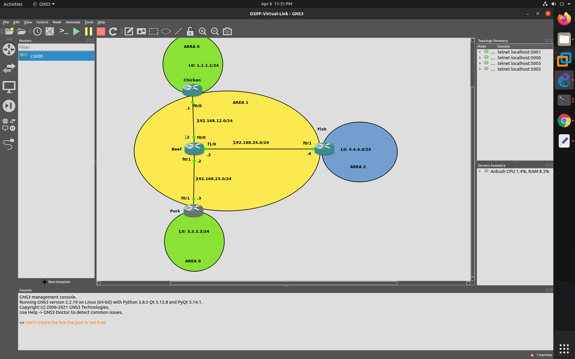
i was doing a lab and i found somting weared, below is the topology

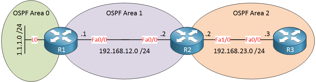
we need to make sure the connectivity between both area0 is there and area 2 has connectivity to backbone area.

but when i configured the lab i am able to access all subnets in all area except area2 loopback,

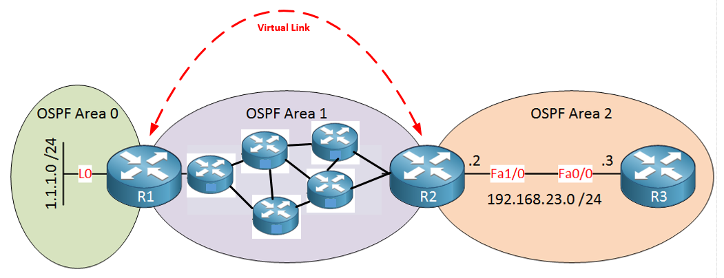
i am able to ping both area0 loopbacks from area2 as well, i think we need virtual link between router pork—>chicken

and one more link between router chicken ----> Fish

i am attaching the config as well please do let me know why it’s behaving like this
Chicken

router ospf 1
 log-adjacency-changes
 network 1.1.1.0 0.0.0.255 area 0
 network 192.168.12.0 0.0.0.255 area 1
 
Gateway of last resort is not set

C    192.168.12.0/24 is directly connected, FastEthernet0/0
     1.0.0.0/24 is subnetted, 1 subnets
C       1.1.1.0 is directly connected, Loopback0
     3.0.0.0/32 is subnetted, 1 subnets
O IA    3.3.3.3 [110/3] via 192.168.12.2, 00:10:49, FastEthernet0/0
O    192.168.24.0/24 [110/2] via 192.168.12.2, 00:10:49, FastEthernet0/0
O    192.168.23.0/24 [110/2] via 192.168.12.2, 00:10:49, FastEthernet0/0
Chicken#

beef

router ospf 1
 log-adjacency-changes
 network 192.168.12.0 0.0.0.255 area 1
 network 192.168.23.0 0.0.0.255 area 1
 network 192.168.24.0 0.0.0.255 area 1

Gateway of last resort is not set

C    192.168.12.0/24 is directly connected, FastEthernet0/0
     1.0.0.0/32 is subnetted, 1 subnets
O IA    1.1.1.1 [110/2] via 192.168.12.1, 00:12:18, FastEthernet0/0
     3.0.0.0/32 is subnetted, 1 subnets
O IA    3.3.3.3 [110/2] via 192.168.23.3, 00:12:18, FastEthernet0/1
C    192.168.24.0/24 is directly connected, FastEthernet1/0
C    192.168.23.0/24 is directly connected, FastEthernet0/1
Beef#

Fish

router ospf 1
 log-adjacency-changes
 network 4.4.4.0 0.0.0.255 area 2
 network 192.168.24.0 0.0.0.255 area 1
 
Gateway of last resort is not set

O    192.168.12.0/24 [110/2] via 192.168.24.2, 00:13:06, FastEthernet0/1
     1.0.0.0/32 is subnetted, 1 subnets
O IA    1.1.1.1 [110/3] via 192.168.24.2, 00:13:06, FastEthernet0/1
     3.0.0.0/32 is subnetted, 1 subnets
O IA    3.3.3.3 [110/3] via 192.168.24.2, 00:13:06, FastEthernet0/1
     4.0.0.0/24 is subnetted, 1 subnets
C       4.4.4.0 is directly connected, Loopback0
C    192.168.24.0/24 is directly connected, FastEthernet0/1
O    192.168.23.0/24 [110/2] via 192.168.24.2, 00:13:06, FastEthernet0/1
Fish#

pork

 router ospf 1
 log-adjacency-changes
 network 3.3.3.0 0.0.0.255 area 0
 network 192.168.23.0 0.0.0.255 area 1
 
Gateway of last resort is not set

O    192.168.12.0/24 [110/2] via 192.168.23.2, 00:11:41, FastEthernet0/1
     1.0.0.0/32 is subnetted, 1 subnets
O IA    1.1.1.1 [110/3] via 192.168.23.2, 00:11:41, FastEthernet0/1
     3.0.0.0/24 is subnetted, 1 subnets
C       3.3.3.0 is directly connected, Loopback0
O    192.168.24.0/24 [110/2] via 192.168.23.2, 00:11:41, FastEthernet0/1
C    192.168.23.0/24 is directly connected, FastEthernet0/1
Pork#

Hello Ankush

You are correct in that you need a virtual link between Chicken and Pork in order to have a single contiguous Area 0. You can see that this is not the case since on Chicken you can see that the route to 3.3.3.3 is considered an Inter Area route since it was learned via an ABR, and thus via a Type 3 LSA. If the virtual link was there, Chicken would have learned about this route directly from Pork (in the same area) over the virtual link.

The second thing you have to do is connect Area 2 to area 0 using a virtual link. You can do this by creating a virtual link between FIsh and Chicken, or between Fish and Pork, the results should be the same…

In particular, the loopback behind fish cannot be seen in any routing tables because area 2 is not directly connected to the backbone area using an ABR. Because Fish has no interfaces on Area 0 it doesn’t fulfil its function as an ABR, since it cannot share LSAs between two non backbone areas. Take a look at the OSPF LSA Types Explained lesson to learn more about how LSAs and their various types are exchanged between areas.

I hope this has been helpful!

Laz

1 Like

Thanks Sir i got it one more question is router Beef a ABR ? because it’s not having any interface in Area0 it’s connected to 2 ABS’s that is Pork and Chicken

Hello Ankush

An ABR is defined as an OSPF router that fulfils the following two criteria:

  1. has at least one interface in Area 0 (backbone area)
  2. has at least one interface in an area other than 0 (non-backbone area)

Therefore Beef is not an ABR since all of its interfaces are in Area 1.

In your topology only Pork and Chicken are ABRs. Without the virtual link, Fish is not even an ABR since it doesn’t have any interfaces on Area 0.

I hope this has been helpful!

Laz

1 Like

Hi Laz,

I am not able to understand these given lines " Imagine the router on top was in area 0. Unfortunately this router crashed and the result is that area 0 is now split into two pieces". How can the area split into two parts when the router crashes?