HSRP will function when configured on physical interfaces of routers or L3 switches or on VLAN interfaces of L3 switches. It will work with VLAN interfaces as I have several implementations where this is the case, as long as the physical interfaces participating in HSRP are access ports in that VLAN or trunk ports that include that VLAN.
Concerning your other comments:
Yes, this is correct. The term “gateway” signifies a L3 interface through which you can reach outside of the local network, such as default gateway or gateway of last resort.
The vast majority of HSRP implementations are used with an L2 switch placed between the host and the two standby routers. This allows for multiple hosts (all hosts in the subnet) to take advantage of the HSRP redundancy. Connecting a host with two network cards to two HSRP routers would rarely be done as it would be somewhat of a waste of resources to provision two routers to redundantly serve only one host. It can be done, but it is definitely not considered good practice.
Quick question. If I have more than 1 SVI interface on a L3 switch, for example, 5 SVI interfaces configured with 5 different subnet masks and wanted to setup HSRP (virtual GW) for each SVI / VLAN for redundancy, would I have to create 5 separate HSRP for each VLAN for redundancy?
My understanding is that I will have to create 5 different HSRPs (Virtual GW) for each SVI/VLAN.
Always glad to help you out and to learn from your experiences as well!
So if you have two L3 switches and you have 5 SVIs configured in each, with the same VLAN numbers and the same subnets, then yes you will require 5 different virtual GW IPs, one for each pair of VLANs.
I have one doubt that if in my network suppose two routers are there and one is having priority 110 (i.e Active) and another router is having priority 90 (i.e Standby) .
If i add one new router to this network with high priority say 140…Which router will become active router with preempt feature enabled on all the routers?
And if preempt is disabled what will happen?
Please guide.
Preempt means that the changes will take into effect right away. Your third router with priority 140 will be elected as the new active router. With preempt disabled, your current router stays the active router.
If there are two switches running HSRP. One is active other is standby..and if we want to upgrade the iOS on both the switches then what steps needs to be taken? Which switch should be upgraded first?
It doesn’t really matter which you will upgrade first. What you can do is force one switch to become active for all VLANs involved by increasing its priority. Once that happens, that one switch will be operating and serving all associated subnets. At that point you can freely make any changes and upgrades you need to the one switch without worrying about affecting the network. Once you get that one upgraded, configure it to be the active router with the appropriate priorities. Once you verify that all networks have indeed switched over and are being served by the newly upgraded switch, you can freely begin upgrading the first switch. Once this is done you can reconfigure the priorities so that HSRP duties are being shared once again between both switches.
I like your simple, to the point explanations. This is another example. Well done!
I never knew about the shutdown option (shutting down the standby group) until reading this article. I’ve always used the decrement command. Under what circumstance would someone use the shutdown command?
Having the ability to shut down the standby group instead of having the priority decremented is just an additional parameter that can be employed in object tracking. There’s no particular scenario (at least that I can think of at this time) where this would function differently than a change in priority.
Hi Rene,
I configured following your topology; however, changed a bit behind R3.
SW1 <—(ospf area 1)–> R3 <—ospf (area 0)—> R4 <—>H2 (172.16.1.2)
SW2 <—(ospf area 2)–> R3 <—ospf (area 0)—> R4 <—>H2 (172.16.1.2)
Everything worked as normal exception of a thing is that
Try this out:
In Rene’s example, he set up two different types of tracking for HSRP. One was interface tracking, the other was IP SLA. You can’t have both enabled at the same time as this will result in unpredictable results. In the lesson, he implements interface tracking, removes it, and then implements IP SLA tracking. First of all, make sure that you have only one or the other.
If you only have one implemented, then I’m guessing that you have the IP SLA configured. What I believe is happening is that the IP SLA you have set up is getting unstable information. Because you have set up the OSPF routing, the IP SLA able to find the 192.168.23.3 address after re-converging. What I think is happening is this:
The Gi0/2 interface of R3 goes down, and initially, the IP SLA is unable to find the 192.168.23.3 address, and the HSRP priorities switch and SW1 becomes active.
OSPF reconverges, and the IP SLA is able to be found via the link between SW1 and R3, and the HSRP then changes priorities, and SW2 becomes active.
When the HSRP changes priorities, traffic is directed to SW2, and therefore IP connectivity to 192.168.23.3 is lost, so it changes priorities again, and SW1 becomes active.
The IP SLA is successful, and the priorities switch again and so on…
Take a look at these as possible reasons and let us know your results!
Thanks for your prompt support.
Yes, you’re correct. And that’s my problem that I’m experiencing with; but I don’t know how to solve it.
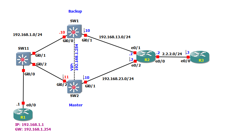
Please see the attached topology for more details.
The target:
R1 can reach R3 through either 192.168.23.0/24 (active) or 192.168.13.0/24 (standby) in case of IP connectivity to 192.168.23.2 is lost (I mean a problem happens on R2 due to IP connectivity or interface e0/2 failure) .
In this scenarios, I have the IP SLA and the static route configured.
Try to test:
R2(config)#interface e0/2
R2(config)#shutdown
The results:
On R1:
R1#ping 2.2.2.3 repeat 20000
Type escape sequence to abort.
Sending 20000, 100-byte ICMP Echos to 2.2.2.3, timeout is 2 seconds:
!!!!!!!!!!!!!!!!!!!!!!!!!!!!!!!!!!!!!!!!!!!!!!!!!!!!!!!!!!!!!!!!!!!!!!
!!!!!!!!!!!!!!!!!!!!!!!!!!!!!!!!!!!!!!!!!!!!!!!!!!!!!!!!!!!!!!!!!!!!!!
!!!!!!!!!!!!!!!!!!!!!!!!!!!!!!!!!!!!!!!!!!!!!!!!!!!!!!!!!!!!!!!!!!!!!!
!!!!!!!!!!!!!!!!!!!!!!!...............................................
.......!!!!!!!!!!!!!!!!!!!!!!!!!!!!!!!!!!!!!!!!!!!!!!!!!!!!!!!!!!!!!!!
!!!!!!!!!!!!!!!!!!!!!!!!!!!!!!!!!!!!!!!!!!!!!!!!!!!!!!!!!!!!!!!!!!!!!!
!!!!!!!!!!!!!!!!!!.!!!!!!!!!!!!!!!!!!!!!!!!!!!!!!!!!!!!!!!!!!.!!!!!!!!
!!!!!!!!!!!!!!!!!!!!!!!!!!!!!!!!!!!!!!!!!.!!!!!!!!!!!!!!!!!!!!!!!!!!!!
!!!!!!!!!!!!!!!!!!!!!!!!!!!!!!!!!!!!!!!!!!!!!!!!!!!!!!!!!!!!!!!!!!!!!!
!!!!!!!!!!!!!!!!!!!!!!!!!!!!!!!!!!!!!!!!!!!.!!!!!!!!!!!!!!!!!!!!!!!!!!
!!!!!!!!!!!!!!!!!!!!!!!!!.!!!!!!!!!!!!!!!!!!!!!!!!!!!!!!!!!!!!!.!!!!!!
!!!!!!!!!!!!!!!!!!!!!!!!!!!!!!!!!!!!!!!!!!!!!!!!!!!!!!!!!!!!!!!!!!!!!!
!!!!!!!!!!!!!!!!!!!!!!!!!!!!!!!!!!!!!!!!!!!!!!!!!!!!!!!!!!!!!!!.!!!!!!
!!!!!!!!!!!!!!!!!!!!!!!!!!.!!!!!!!!!!!!!!!!!!!!!!!!!!!!!.!!!!!!!!!!!!!
!!!!!!!!!!!!!!!!!!!!!!!!!!!!!!!!!!!!!!!!!.!!!!!!!!!!!!!!!!!!!!!!!!!!!!
!!!!!!!!!!!!!!!!!!!!!!!!!!!!!!!!!!!!!!!!!!!!!.
-
SW2(config)#
*May  5 17:52:04.559: %TRACK-6-STATE: 1 ip sla 1 state Up -> Down
*May  5 17:53:04.561: %HSRP-5-STATECHANGE: Vlan1 Grp 1 state Active -> Speak
*May  5 17:53:04.935: %HSRP-5-STATECHANGE: Vlan1 Grp 1 state Speak -> Standby
*May  5 17:53:07.911: %HSRP-5-STATECHANGE: Vlan1 Grp 1 state Standby -> Active
*May  5 17:53:08.052: %HSRP-5-STATECHANGE: Vlan1 Grp 1 state Active -> Speak
*May  5 17:53:08.385: %HSRP-5-STATECHANGE: Vlan1 Grp 1 state Speak -> Standby
*May  5 17:53:09.944: %HSRP-5-STATECHANGE: Vlan1 Grp 1 state Standby -> Active
*May  5 17:53:10.027: %HSRP-5-STATECHANGE: Vlan1 Grp 1 state Active -> Speak
*May  5 17:53:10.318: %HSRP-5-STATECHANGE: Vlan1 Grp 1 state Speak -> Standby
*May  5 17:53:12.116: %HSRP-5-STATECHANGE: Vlan1 Grp 1 state Standby -> Active
Turn on the interface e0/2 on R2:
R2(config)#interface e0/2
R2(config)#no shut
On SW1:
SW1#
*May  5 17:57:23.239: %HSRP-5-STATECHANGE: Vlan1 Grp 1 state Standby -> Active
*May  5 17:57:23.566: %HSRP-5-STATECHANGE: Vlan1 Grp 1 state Active -> Speak
*May  5 17:57:23.914: %HSRP-5-STATECHANGE: Vlan1 Grp 1 state Speak -> Standby
*May  5 17:59:51.227: %HSRP-5-STATECHANGE: Vlan1 Grp 1 state Standby -> Active
*May  5 17:59:51.366: %HSRP-5-STATECHANGE: Vlan1 Grp 1 state Active -> Speak
*May  5 17:59:51.702: %HSRP-5-STATECHANGE: Vlan1 Grp 1 state Speak -> Standby
Because of this state when executing ping from R1 to R3 some icmp package will be lost.
In this case, you shouldn’t use the IP SLA in order to determine which switch will be active. Because OSPF gives you alternatives when it reconverges, this is not a good test. You should use interface tracking, which is the first option that is described in the lesson. That way if the link on the Gi0/2 interface of SW2 goes down, the HSRP active device will change and will not flap.
In general, the mechanism used to determine which switch should be active in HSRP should me a stable one.
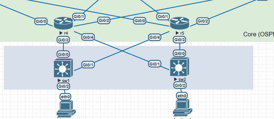
HSRP can be run between multiple routed interfaces. This means that you can have HSRP run between two SVIs on two layer 3 switches, or between two routed ports on two routers. Since you need to run HSRP between two routers, then you must run it between to specific ports on those routers.
If you are to keep the topology as it is, the best solution is not to use HSRP or VRRP, but to use redundant routing between your L3 switches and your R4 and R5 routers. However, if you must use a redundant gateway protocol, then you can have Gi0/3 of R4 and Gi0/4 or R5 run HSRP between them and Gi0/4 of R4 and Gi0/3 of R5 run HSRP between them as well. This way SW1 will have a redundant gateway configured for both its upstream interfaces as will SW2. This is not the best design however.
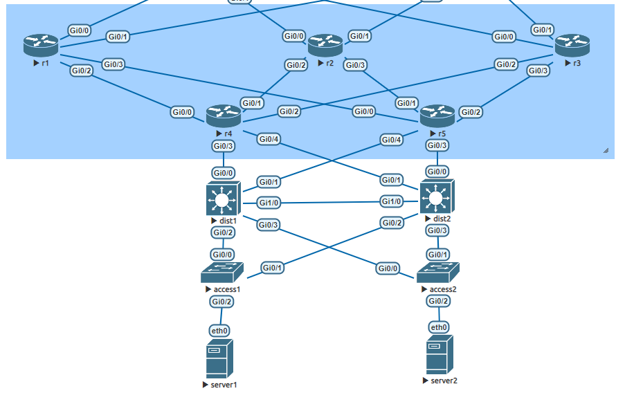
HSRP and VRRP are more suited to be used as redundant default gateways for internal users. So here the best thing to do design-wise is to have SW1 and SW2 have SVIs that server internal users that run HSRP or VRRP between them. You would also need an additional access layer of switches (between the hosts and SW1 and SW2) that will allow the hosts to have access to both SVIs in the event that one fails. You can then have redundant routing set up between the two L3 switches and the two L3 routers.
Take a look at this lesson for more information about campus network design: