I am trying to understand the purpose of having an ip address on the physical interface and for Hsrp. Is the Hsrp virtual ip address used for routing protocols, or is the physical ip address used?
I think this is the answer. Q. is it possible to run hsrp and ospf together on the backbone router.
HSRP requires that the interfaces participating in the hot standby configuration have a physical IP address. This is because this address is still used (as you correctly stated) for routing protocols as well as for some ICMP functionality such as traceroute. HSRP was designed in this fashion.
As for using dynamic routing protocols with HSRP, yes, you can use them. The virtual IP will not be the one participating in the protocol, but the physical IPs of the interfaces. As you state, when using OSPF with HSRP, the answer given in the Cisco documentation answers your question. The active router will send a gratuitous ARP informing the LAN segment of the virtual IP and MAC corresponding to itself. The same is true of EIGRP.
regarding hello timer and hold timers.
I have configured 5 & 15 in HSRP Active router R1 and i configured 10 & 30 in HSRP standby router R2.
R1
!
interface FastEthernet0/0
 ip address 10.10.10.5 255.255.255.0
 duplex auto
 speed auto
 standby version 2
 standby 1 ip 10.10.10.6
 standby 1 timers 5 15
!
interface FastEthernet1/0
 ip address 192.168.1.1 255.255.255.0
 duplex auto
 speed auto
!

R1# SHow STANdby
FastEthernet0/0 - Group 1 (version 2)
  State is Standby
    38 state changes, last state change 01:52:20
  Virtual IP address is 10.10.10.6
  Active virtual MAC address is 0000.0C9F.F001
    Local virtual MAC address is 0000.0C9F.F001 (v2 default)
  Hello time 10 sec (cfgd 5 sec), hold time 30 sec (cfgd 15 sec)
    Next hello sent in 7.137 secs
  Preemption disabled
  Active router is 10.10.10.7, priority 100 (expires in 25 sec)
    MAC address is 0000.0C9F.F001
  Standby router is local
  Priority 100 (default 100)
  Group name is hsrp-Fa0/0-1 (default)

R2
!
interface FastEthernet0/0
 ip address 10.10.10.7 255.255.255.0
 duplex auto
 speed auto
 standby version 2
 standby 1 ip 10.10.10.6
 standby 1 timers 10 30
 standby 1 track FastEthernet1/0
!
interface FastEthernet1/0
 ip address 192.168.2.1 255.255.255.0
 duplex auto
 speed auto
 standby 0 track FastEthernet1/0
!`Preformatted text`

R3#SHow STANdby
FastEthernet0/0 - Group 1 (version 2)
  State is Active
    22 state changes, last state change 01:50:10
  Virtual IP address is 10.10.10.6
  Active virtual MAC address is 0000.0C9F.F001
    Local virtual MAC address is 0000.0C9F.F001 (v2 default)
  Hello time 5 sec (cfgd 10 sec), hold time 15 sec (cfgd 30 sec)
    Next hello sent in 4.449 secs
  Preemption disabled
  Active router is local
  Standby router is 10.10.10.5, priority 100 (expires in 8 sec)
  Priority 100 (default 100)
    Track interface FastEthernet1/0 state Up decrement 10
  Group name is hsrp-Fa0/0-1 (default)
R1 is sending hello messages every 5 sec. and R2 is sending hello messages every 10sec. if both routers are sending hello messages in different intervals will it effects any packet drops or any switching issue?
When you configure different timers in two HSRP routers, it is always the timers on the active router that override those of the standby router. If you notice in the output of the show standby command on R1, you see the following:
Hello time 10 sec (cfgd 5 sec), hold time 30 sec (cfgd 15 sec)
Although 5 and 15 are configured, 10 and 30 are being used which are those configured on the active device.
Best practice however dictates that you should make sure the timers are the same across all HSRP devices in order to avoid any problems. The problems may occur when a standby device becomes active. Once that happens, the timers of the active device are now being used. This may cause a longer convergence time when changes take place.
So even if the timers are not the same, you should not see any packet drops or switching issues during normal operation, but you may see an increase in convergence time in the event of a failure.
Hi Rene/Laz
I’m playing around with the topology in your GNS3Vault HSRP page and
I’ve got router NewJersey (192.168.1.2) as active
preemption enabled
All routers having priority of 100
so I believe LA (192.168.1.3) should automatically take over as the active router, but it isn’t. Am I correct in thinking it should take over as soon as preemption is enabled? If so, do you have any suggestions as to why it isn’t?
When you enable preemption for HSRP, it only functions for the priority criterion. What I mean is, if all routers have a priority of 100, then it is as if preemption is not configured. Preemption will only be triggered if one router has a higher priority than the other. The higher IP address is not something that will trigger preemption, but is only used for the initial choosing of the active router.
I have a simple network setup in my environment with 2 * 2960X LAN Base license which has uplinks to 2 * 4321 routers which further has uplinks to 2 different ISP links. Router1 is connected to ISP 1 and Router 2 is connected to ISP 2. I am planning to run HSRP on my routers internal interface connected to switches so that the users can have gateway level redundancy. So I should have to configure the switch uplink interfaces on both my switches as trunk and interface between the switches has trunk right and then configure the L3 interface as HSRP.
R1    HSRP    R2
!             !
!             !
SW1----------SW2
I read in some posts that 2960X with LAN base license does support minimum routing but I am not how far its true. Need your advise on the above.
First of all, LAN base images support only Layer 2 functionality. They don’t support any routing. You can see this from the 2960 datasheet below:
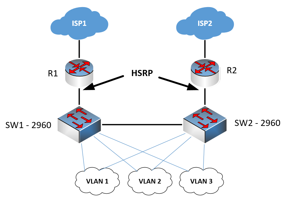
As such, the LAN base images of the 2960 are not capable of performing HSRP. This means that HSRP must be employed between the two 4321 routers. Since these router will have to perform all the routing for the internal network as well, you will require the enterprise-network-facing interfaces of the routers to have subinterfaces, and it is these subinterfaces that you can enable HSRP on. Here is an example topology:
In this case, you would configure the uplinks from the switches to the routers as trunks, and the subinterfaces of the routers would function using HSRP. You would also create a trunk between the two switches that carries all the VLANs so that hosts on SW2 will be able to reach R1 in the event that R2 fails, and similarly, hosts on SW1 will be able to reach R2 in the event that R1 fails.
In this case, you must create multiple HSRP pairings between the subinterfaces on each router that correspond to each VLAN.
Now this topology will work, but it is not ideal, because the routers are performing both routing for internal VLANs, as well as routing to the Internet. Ideally, internal routing should be taken care of by a different device, and not by the edge router. If the switches were L3 switches, then you could run HSRP on the SVIs on the switches themselves so that all internal routing is taken care of there, while routing to the Internet would be taken care of by the edge routers.
Thanks for the detailed explanation. I do understand the requirement of having L3 switch for internal vlan routing but the client network is very small I hardly have maximum 2 internal subnet. This might even come down to 1 LAN subnet. So that I can create one L3 interface on router to point the traffic to VIP as gateway and then WAN side routing on my router uplinks. I would also like to know whether this 2960x LAN Base image support IP helper command or dhcp relay command to configure on my switches.
Yes, this is correct. If your switches will only function in Layer 2 then you can simply create subinterfaces on the LAN facing interfaces of the routers, one for each internal VLAN. Then you can create trunks to each router from the switches, and a trunk between the switches carrying all VLANs. This will be sufficient to allow any device connected to an L2 switch to reach either one of the routers using HSRP.
If the switches are Layer 2, then they can’t use the IP helper address feature. This feature is used by the default gateway of the particular subnet in order to relay DHCP requests to the DHCP server that is found on another subnet. If the switches function in Layer 2, then you cannot employ the IP helper address feature.
-Lazaros Agapides
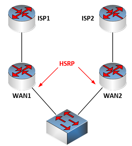
Thanks for the explanation. I have ISP-1 is connected to WAN router-1 and ISP-2 is connected to WAN router-2 and I want to achieve the HA between these two ISP. From LAN side I have only one VLAN/subnet which have the default gateway configure in routers, with this setup will I be able to achieve the load sharing on the WAN side (both ISP link to be used ) with single LAN subnet in use.
And there is only a single VLAN on the switch. If this is the case, and your WAN routers are IOS routers, then there is no way, using HSRP, to perform load balancing. Each subnet will have to choose one of the WAN routers as the active gateway. If you had more VLANs, you could create subinterfaces and have one WAN router be active on one VLAN, and the other be active on the other VLAN.
There are two solutions for this:
If your WAN routers are Nexus layer 3 switches connected via vPC, then HSRP does indeed perform load balancing between the two without any additional configurations.
Instead of HSRP, use Gateway Load Balancing Protocol (GLBP). As its name suggests, it automatically performs load balancing. All Cisco routers support it (as far as I know) so you shouldn’t have a problem implementing it. Load balancing can also occur using multiple algorithms, but you can read more about that in the lesson link above.
Yes, the topology is correct. The problem here is the Layer 2 we have here is cisco 2960X with LAN base license which doesn’t have routing capability and on the WAN side we have cisco 4221 and on the LAN side we have only one VLAN to achieve LAN balance on both LAN and WAN side.
Is there any way we can utilize both the links at the same time on the WAN side?
You should be able to enable GLBP between the two 4221 routers, which will enable load balancing. This would probably be the most effective and fastest load balancing implementation without requiring the replacement of equipment. Take a look at the GLBP lesson for more details on how to set that up.
Consider this setup is HQ along with firewall connect to Layer 2 switch, only internet traffic passes thru the firewall. For intranet it would traverse via WAN cloud and we have similar setup in branch office but in branch we do not have firewall, internet access for branch would traverse take below path.
BR SW → BR RTR → BR WAN → HQ WAN —> HQ RTR —> HQ SW —> HQ FW —> Internet
I think I have to inject the default route in BGP on the branch office router towards the HQ WAN or I am not sure how can I achieve the above setup successfully.
If your intranet is all contained behind the firewall, this means that all internal communication, including that over the WAN, will be achieved with internal routing. You wouldn’t use BGP to achieve this, but an IGP such as EIGRP or OSPF. If you use BGP, you would use it at the network edge, specifically at the firewall or on any routers between the firewall and the internet.
I’m not sure why you would want to use BGP on this topology. Can you describe what you are trying to achieve so that we can help you further?
All the HQ, BR have their own WAN connectivity ( 2 ISP’s terminated into 2 WAN RTR ) respectively. But internet link is terminated only in HQ. All the branches have to come to HQ via WAN and then to HQ FW to reach the internet
Branch Internet
BR SW → BR WAN → WAN Cloud → HQ WAN → HQ SW → HQ FW → Internet
HQ Internet
HQ SW → HQ FW → Internet
Please suggest a solution to achieve the connectivity.