Renee / Lagapides
A question please i have read on this forum as follows:
It is possible to have SVIs on multiple switches be in the same subnet, and depending on how you have set up your network, you can make any one of those SVIs a default gateway for use by the hosts on the
192.168.1.0/24 subnet…
So based on above can you clarify please further do you mean this can be done also when stretching across 2 x core switches but where those core switches route in different routing domains so to speak EG what if you have 2 x core switch that are for example EBGP peers (different AS) with L2 direct connection which could trunk VLaNs (if required). So I then want to deploy a single but SAME subnet say 10.1.1.x/24 where x is constant and want to stretch that across each individual respective campus is it possible ? And secondly how would SVI,s be numbered ie would you use a .1 on each core switch SVI interface (my wider reading suggests it’s never good practice to stretch or span vlans) I labbed this in gns and it seemed to work to a point through a vlan add to the layer 2 trunk adjoining each core switch (presumably no spanning issues as port channel) i connected and configured hosts in same subnet either side of core switch directly connected as well as other test subnets (so 10.1.2.x & 10.1.3.x) - it seemed to work configuring only a single svi on one core switch for the subnet with vlans added both sides and to the layer 2 trunk I could ping between all hosts but also works for svi on both core switch with some success) which would you or could you do if any but on bgp I could only think to configure host routes /32 to null 0 to push into bgp to allow specific L3 routing updates beyond the core network so traffic destined for each directly connected /32 host within the subnet gets explicitly routed to the correct core switch - this shaped up to a point however, bgp route should propagated to core peers for same respective subnet would show in local ip bop table but would be unreachable ‘U’ / !H … sorry long question I know but this is a response to the statement by lagapides and confusion caused by the rhetoric surrounding spanning or stretching layer 2 clans beyond the core - await any input on this’ll most appreciated hope this makes sense - ps I think this touches on a wider design issue however also focusses as a good example on the specific use case for svi and also incorporates the use case of actually routing svi as well whereas all education often point should to handling routed vlans separately from l3 side many thank so will
Happy to provide my example lab and diagram if helps I really have spent long time reading on this on your site and wider sources but I’m not sure what is allowed or should be allowed and most importantly if vlans have to be stretched (spanned is different I think) what is the right / best way to do it. (Assuming a subnet has to Ben stretched)
Hello William
You have touched on many subjects in your post, so I will attempt to respond as best I can.
The original comment concerning the SVIs was mine I believe. An example of what I mean can be seen in the following simple topology with layer 3 switches:
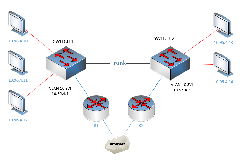
So here we have two switches, each with an SVI on VLAN 10, having IP addresses 10.96.4.1 and 10.96.4.2 respectively. Each switch is connected to a router on a different VLAN to which it sends all default route traffic. So, each PC connected to VLAN 10 can have either a default gateway of 10.96.4.1 or 10.96.4.2. Each choice has a different routing choice.
This scenario is indeed an unusual implementation. The point is however, that it is possible to configure.
Now in order to respond more clearly to the rest of your queries, it would be helpful to provide us with a topology and specific problems or issues that you are facing so we can more effectively help you.
I hope this has been helpful!
Laz
Say I had a 2960 switch with 24 host. All the host are in the same VLAN 123 (same subnet). There will be no other VLANS on that switch. That switch is connected to a router. That link connected to the router – would that switchport on the switch be a trunk port or and access port?
Hi Jason,
If you only have one VLAN then you can configure the switchport to the router as an access port that is assigned to VLAN 123. Technically, you could also use a trunk (with only VLAN 123) but it’s not needed since you only have one VLAN.
If you have two VLANs and you want to use your router as a default gateway for your hosts, that’s when you need a trunk between the switch and router.
Hope this helps!
Rene
Hi Rene,
Hope you are doing good..
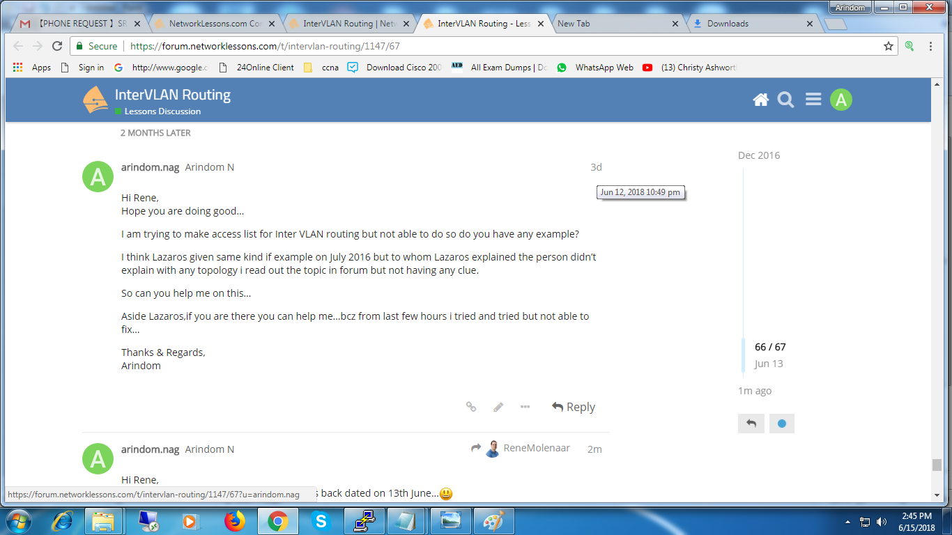
I am trying to make access list for Inter VLAN routing but not able to do so do you have any example?
I think Lazaros given same kind if example on July 2016 but to whom Lazaros explained the person didn’t explain with any topology i read out the topic in forum but not having any clue.
So can you help me on this..
Aside Lazaros,if you are there you can help me..bcz from last few hours i tried and tried but not able to fix..
Thanks & Regards,
Arindom
Hi Rene,
Hope you are doing good..Can you help me please…i asked you 2 days back dated on 13th June…![]()
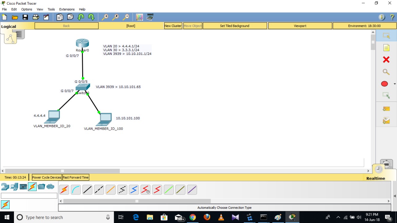
ACL for Inter VLAN routing…Based on my LAB topology requirement is,
Condition1,
Network 3.3.3.0/24(VLAN30),4.4.4.0/24(VLAN20) …will ping to each other.
Condition2,
the network 10.10.101.0/24(VLAN3939) should not ping to the other or other network shold not ping to 10.10.101.0/24(VLAN3939)
NOTE:Here vlan20 & 30 is service vlan & Vlan3939 is management vlan for switches reach-ability from backhand,Main agenda is from downside network services vlan will not ping to switches.
Thanks & Regards,
Arindom
Hello Arindom
Based on your description, I am making the following assumptions:
- the link between the router and the switch is on VLAN 30
- The SVI of VLAN 30 on the switch has an IP address of 3.3.3.1
Now if this is the case, then we can proceed looking at the conditions.
For this condition, we don’t have to do anything, since by default, communication between VLANs on a layer 3 switch occurs as long as the SVIs are configured and as long as the correct default gateways are configured on the devices themselves.
Now from my understanding, you want to completely isolate VLAN 3939 from all other VLANs. So no communication from 3939 to 20 or 30 and no communication from 20 or 30 to 3939. This means that you want to block all traffic to and from the VLAN 3939 SVI. You can do this by creating the following ACLs
access-list 101 deny any any
access-list 102 deny any any
and placing it both incoming and outgoing on the VLAN 3939 interface like so:
interface VLAN 3939
  access-group 101 in
  access-group 102 out
Now if at some point you choose to provide access to another VLAN from the 3939 VLAN, you can always add specific IP address ranges that you will allow. This is why I created two separate ACLs, so that you can more specifically specify the incoming and outgoing traffic.
I hope this has been helpful!
Laz
Hi Laz,
Thanks for answering me…
As per your above mentioned configuration line Today i did test with my LAB simulator and its working fine but i have few questions so tomorrow i will send you.
Thanks & Regards,
Arindom
Hello Arindom
Great to hear that it’s up and running!
I’m looking forward to your questions. Talk soon!
Laz
Hi Laz,
As i told you Which configuration you suggested its working but i did tried with different way so i want to understand what is the difference between your cfg & my cfg,
Below mention is my cfg & topology is attached for your reference…
Router----
interface FastEthernet0/0.20
 encapsulation dot1Q 20
 ip address 2.2.2.1 255.255.255.0
!
interface FastEthernet0/0.30
 encapsulation dot1Q 30
 ip address 3.3.3.1 255.255.255.0
!
interface FastEthernet0/0.100
 encapsulation dot1Q 100
 ip address 10.10.101.1 255.255.255.0
 ip access-group 2 out


interface FastEthernet0/0.20
 encapsulation dot1Q 20
 ip address 2.2.2.1 255.255.255.0
!
interface FastEthernet0/0.30
 encapsulation dot1Q 30
 ip address 3.3.3.1 255.255.255.0
!
interface FastEthernet0/0.100
 encapsulation dot1Q 100
 ip address 10.10.101.1 255.255.255.0
 ip access-group 2 out

access-list 2 permit 10.10.101.0 0.0.0.255
access-list 2 deny any
PC2 Under VLAN 30
PC2>ping 2.2.2.2

Pinging 2.2.2.2 with 32 bytes of data:

Reply from 2.2.2.2: bytes=32 time=0ms TTL=127
Reply from 2.2.2.2: bytes=32 time=1ms TTL=127
Reply from 2.2.2.2: bytes=32 time=0ms TTL=127
Reply from 2.2.2.2: bytes=32 time=0ms TTL=127

Ping statistics for 2.2.2.2:
    Packets: Sent = 4, Received = 4, Lost = 0 (0% loss),
Approximate round trip times in milli-seconds:
    Minimum = 0ms, Maximum = 1ms, Average = 0ms


PC2>ping 10.10.101.65

Pinging 10.10.101.65 with 32 bytes of data:

Reply from 3.3.3.1: Destination host unreachable.
Reply from 3.3.3.1: Destination host unreachable.
Reply from 3.3.3.1: Destination host unreachable.
Reply from 3.3.3.1: Destination host unreachable.

Ping statistics for 10.10.101.65:
    Packets: Sent = 4, Received = 0, Lost = 4 (100% loss),

PC2>ping 10.10.101.101

Pinging 10.10.101.101 with 32 bytes of data:

Reply from 3.3.3.1: Destination host unreachable.
Reply from 3.3.3.1: Destination host unreachable.
Reply from 3.3.3.1: Destination host unreachable.
Reply from 3.3.3.1: Destination host unreachable.

Ping statistics for 10.10.101.101:
    Packets: Sent = 4, Received = 0, Lost = 4 (100% loss),
PC3 Under VLAN 100
PC3>ping 2.2.2.2
Pinging 2.2.2.2 with 32 bytes of data:
Request timed out.
Request timed out.
Request timed out.
Request timed out.
Ping statistics for 2.2.2.2:
Packets: Sent = 4, Received = 0, Lost = 4 (100% loss),
PC3>ping 3.3.3.3
Pinging 3.3.3.3 with 32 bytes of data:
Request timed out.
Request timed out.
Request timed out.
Request timed out.
Ping statistics for 3.3.3.3:
Packets: Sent = 4, Received = 0, Lost = 4 (100% loss),
PC3>ping 10.10.101.1
Pinging 10.10.101.1 with 32 bytes of data:
Reply from 10.10.101.1: bytes=32 time=0ms TTL=255
Reply from 10.10.101.1: bytes=32 time=0ms TTL=255
Reply from 10.10.101.1: bytes=32 time=0ms TTL=255
Reply from 10.10.101.1: bytes=32 time=0ms TTL=255
Ping statistics for 10.10.101.1:
Packets: Sent = 4, Received = 4, Lost = 0 (0% loss),
Approximate round trip times in milli-seconds:
Minimum = 0ms, Maximum = 0ms, Average = 0ms
PC3>ping 10.10.101.65
Pinging 10.10.101.65 with 32 bytes of data:
Reply from 10.10.101.65: bytes=32 time=0ms TTL=255
Reply from 10.10.101.65: bytes=32 time=0ms TTL=255
Reply from 10.10.101.65: bytes=32 time=0ms TTL=255
Reply from 10.10.101.65: bytes=32 time=0ms TTL=255
Ping statistics for 10.10.101.65:
Packets: Sent = 4, Received = 4, Lost = 0 (0% los

Thanks & Regards,
Arindom
Hello Arindom
There are two fundamental differences between your config and mine. Your config is what is called a “router on a stick” where the routing takes place in the router itself. This means that any traffic from VLAN 10 to VLAN 20 for example will go to the router, be routed from the Fe0/0.10 interface to the Fe0/0.20 interface, be sent back to the switch and to the appropriate device on VLAN 20.
My config involves interVLAN routing, which is routing from one VLAN to another within the Layer 3 switch itself. In this case, routing takes place from one SVI to another, for the specific example, from the VLAN 10 interface to the VLAN 20 interface on the switch itself.
The other fundamental difference is the location and type and direction of the access lists that have been applied. In my example, I used two EXTENDED access lists that can deny or permit packets based on their source AND destination addresses, while you used a STANDARD access list that filters traffic based ONLY on the source address.
By creating two access lists and placing them on the SVI of the subnet you want to isolate and specifying that we want both directions (in and out) to be blocked AND we want to block packets regardless of source or destination IP, we verify that no traffic can go in our out of this subnet.
What you have done is created a single access list that filters based on source IP address only and filters only traffic flowing into VLAN 100.
So, when you get this result:
the ping reaches the Fe0/0.100 interface, but because the access list blocks the ping, the router responds and says that it can’t reach the destination.
When you get:
The ping goes to the router, gets routed, reaches PC2, and PC2 responds. The response reaches the router, but because of the access list on the Fe0/0.100 interface in an outgoing direction blocks it, the packet never returns and thus you get a request timed out.
PC3 can ping anywhere within the subnet (10.10.101.X) because you are not directing any traffic to the interface where the access list has been installed.
I hope this has been helpful!
Laz
Why would we want to assign more than one IP address subnet to a single SVI? I noticed they do this at my work for redundancy. The additional IP address show up as “secondary” on a show run. Is this a common practice? Can more than one IP address subnet be assigned to a physical interface (not including sub- interfaces – router on a stick)?
Hello Jason
It is indeed a rare occurrence to have two or more IP addresses assigned to a single interface, whether SVI or physical. There are however some situations where it can be useful. Before I mention those, let me answer your question:
Typically, good network design dictates that each VLAN should contain a single subnet. It is possible however to have two or more subnets share the same broadcast domain/VLAN/network segment. This is done by adding another IP address in a different subnet to the same SVI. So you can have 10.10.10.1/24 and 10.10.20.1/24 assigned to a single SVI. All hosts within the VLAN will have one of the following two configurations:
-
IP address between 10.10.10.2 and 10.10.10.254, subnet mask 255.255.255.0 and default gateway 10.10.10.1
-
IP address between 10.10.20.2 and 10.10.20.254, subnet mask 255.255.255.0 and default gateway 10.10.20.1
Both subnets will coexist on the same VLAN and the SVI will be used as the default gateway in both cases. Even communication between hosts in each VLAN must go through the SVI to be routed. This in general is not good network design but it can be done. Note however that all broadcasts sent from one device will be “heard” by all hosts in the VLAN regardless of which subnet they belong to. Remember that although there are two subnets, they coexist in the same VLAN/network segment/broadcast domain.
Cisco suggests some situations in which secondary addresses are useful in this Cisco documentation.
I’m interested to find out how a secondary IP address on an SVI serves to provide redundancy? Can you elaborate on that?
I hope this has been helpful!
Laz
Hi Rene and staff,
i just want to add a comment about the conclusion of the section “routed ports”
I hope i am right, and my comment will be useful
"
What should you use? The SVI or the routed port? If you only have one interface in a VLAN it’s fine to use the routed port, configure an IP address on it and you are ready to go. If you have multiple interfaces in a VLAN you should use the SVI.
"
Look at my small lab
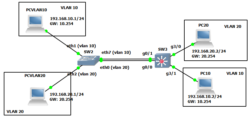
SW3 has ports in vlan 10 (and ports in vlan 20): in this case you cannot use g0/1 ou g0/0 as routed ports because in this case PCVLAN10 can’t communicate with PC10 (and PCVLAN20 also cannot ping PC20). Because the routed ports cannot forward the trames to access ports g3/0 (or g3/1) that are in access vlans. You have no choice: g0/0 and g0/1 must be switchport and you have to use SVI (int vlan 10 and int vlan 20) as GW to make inter-vlan routing
So “If you have multiple interfaces in a VLAN you should use the SVI”: it seems that it is a better way than to use routed ports (but i am french and i hope my translation is right). But in my opinion (see my small lab), in this case, you cannot use routed ports to make intervlan-routing
Note: in real world, you should replace the 2 links between the SW by a trunk
Regards
Hello Dominique
Yes, you are correct in your explanation. You can also look at it this way: If you have a routed port on a L3 switch, then that port will function exactly the same way as a port on a router. You would require an L2 switch to connect to that routed port in order to connect multiple devices to that subnet.
Thanks for your comments, it clarifies the point even more and adds value to the forum!
Laz
Hi Rene, Appreciate your efforts to make simple and excellent explanation of network.

If I have two L2 links between two switches then how can I achieve static routing or ospf routing. Any STP issues ? Can I use both the links as active/active or active/ standby ?
Hello Nityanand,
You need routing only if packets have to leave one vlan/subnet and enter another vlan/subnet. Routed ports and SVIs behave as default gateway for these packets, they re-write layer 2 header informations.
If you have 2 links inter-connecting 2 switches and all 4 endpoinds of these links are switchports, then STP will put one of these switchpors into blocking state. STP is operating only on switchports. Routed ports and SVIs are not sending STP BPDUs, neigher understand them, they just drop STP ingress traffic.
You can overcome this STP blocking state by bundling this two inter-connecting links into Etherchannel. STP runs on top of Etherchannel, so these two physical links will appear as just one link for STP, therefore STP will not block any of link endpoints.
You can study more about Etherchannels in following lecture:
And more about STP:
https://networklessons.com/switching/introduction-to-spanning-tree
Sorry, that my answer is such universal, but i didnt really get what you are asking for. Can you be more specific, may be post image of your topology, so I can help you?
Thank You Fugazz, Much appreciated your response.
https://networklessons.com/cisco/ccie-routing-switching/intervlan-routing.
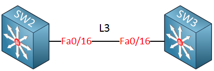
In this image, fa0/16 single link failure, if i add one more interface fa0/17 and create portchannel.
Hi Nityanand,
this “L3” written over the line means that both link end-points on switches are routed ports. We can add one more link interconnecting switches, make both of its end-points routed ports. Bundle links together, add IP on each end-point of port-channel and then run OSPF over it. It is no problem, should look like this.
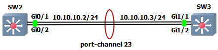
Create virtual port-channel interface, make it routed port-channel and add IP on it.
SW2(config)# interface port-channel 23
SW2(config-if)# no switchport
SW2(config-if)# ip address 10.10.10.2 255.255.255.0

SW3(config)# interface port-channel 23
SW3(config-if)# no switchport
SW3(config-if)# ip address 10.10.10.3 255.255.255.0
Make physical interfaces routed ports and bundle them into port-channel. You can use interface range command for it.
SW2(config)# interface range g0/1 - 2
SW2(config-if-range)# no switchport
SW2(config-if-range)# channel-group 23 mode on

SW3(config)# interface range g1/1 - 2
SW3(config-if-range)# no switchport
SW3(config-if-range)# channel-group 23 mode on
Port-channel should be up, you can try some verification commands.
SW2# show etherchannel 23 summary

<..output omitted..>

Group  Port-channel  Protocol    Ports
------+-------------+-----------+-----------------------------------------------
23     Po23(RU)         -        Gi0/1(P)    Gi0/2(P)
Enable IP routing on both switches.
SW2(config)# ip routing

SW3(config)# ip routing
Run OSPF process on created L3 port-channel interfaces. For example like this.
SW2(config)# router ospf 1
SW2(config-router)# network 10.10.10.2 0.0.0.0 area 0

SW3(config)# router ospf 1
SW3(config-router)# network 10.10.10.3 0.0.0.0 area 0
OSPF adjancency should come up. You can verify it.
SW2# show ip ospf neighbor

Neighbor ID     Pri   State           Dead Time   Address         Interface
10.10.10.3        1   FULL/DR         00:00:36    10.10.10.3      Port-channel23
Edit:
Notice that ip address is configured only on virtual port-channel. There is no ip address configured on physical routed ports.
In case you shutdown one physical interface then port-channel stays up. Verify it like this.
SW2(config)# interface g0/2
SW2(config-if)# shut

SW2# show etherchannel 23 summary
Group  Port-channel  Protocol    Ports
------+-------------+-----------+-----------------------------------------------
23     Po23(RU)         -        Gi0/1(P)    Gi0/2(D)
Pay attention to letters in brackets.
- Po23(RU), R means that it is layer 3 portchannel and U means that its status is up (working).
- Gi0/1(P ), P means that interface G0/1 is active and still bundled.
- Gi0/2(D), D tells us that interface is down, well because we did shut it down.
Is this what you was looking for?