Hi Fugazz, Thank You for quick response. Much appreciated.
Yes, you made it clear. In my case one end Cisco 3750 and other end Aurba os 16.6 so not sure about creating l3 portchannel. If you know this or find something, please let me know. Thank you again.
Kudos to @fugazz for his explanation, clear, comprehensive and correct! As for connecting a 3750 to an Aruba device it is possible to create a port channel. You can do this either by statically configuring it on both ends or by using the Link Aggregation Control Protocol (LACP) to negotiate aggregation, which is an open protocol supported by Cisco and many other vendors. Don’t use PAgP as this is Cisco proprietary.
You can find out more about link aggregation at the lesson posted by @fugazz.
The reason you’re getting the error for this command is because the specific switch is a layer 2 switch. This means that its ports cannot operate any layer 3 mechanisms or configurations, therefore they cannot be assigned an IP address. A layer 2 switch can only have an IP address assigned to its VLAN interface more correctly referred to as a Switched Virtual Interface (SVI). In order to assign an IP address to an interface, you require a Layer 3 switch where you can convert a switchport to a routed port and assign the IP address. Or of course, if you use a router, which can have its ports assigned an IP address.
Hi,
I have Cisco Catalyst 3650 switches. I would like to find out how to configure hosts in VLAN 10 & VLAN 20 both talk to VLAN 50’s hosts, but not between each other (VLAN 10 & VLAN 20). If you have video or discussion about it, please let me know. Thank you for your help.
If you have various hosts on different VLANs on a Layer 3 switch, these hosts will automatically be able to communicate with each other through InterVLAN routing. If however you want to block certain communications between them, then you can use access lists to do so. Take a look at these two lessons. They involve access lists on routers, but the concept is the same for Layer 3 switches:
Why do you have to assign the vlan for an SVI on an access or trunk port? isn’t a SVI a layer 3 port?
It would seem like you should be able to connect to an SVI just like a router port. What is the point of having that random access port up or an allowed vlan over a trunk when you have an SVI(layer 3 port) to let the traffic in? I have done a good bit of googling, and I am honestly not sure where to look.
When you have a L3 switch, you have the following two options for creating routed interfaces:
Make one of the physical ports a routed interface using the no switchport command, and then assign an IP address to the port. This will actually make the physical port function like the port of a router, with an IP address and subnet mask on the interface itself.
Create an SVI and assign it an IP address. Now if you do this, you create a virtual interface. This virtual interface has no connection to a physical device in any way UNLESS you create an access or trunk port on the same VLAN as the SVI via which end devices can communicate with the SVI. There is no other physical way for a device, such as a PC, to access that IP address and use it as the default gateway.
My question is regarding inter-vlan routing. The short, do all L2 and L3 switches need svi to have a svi with the appropriate vlan, ip address and vlan for inter vlan routing to work? In a three tier Cisco networking framework, Can the access switch have the vlan(s) configured and the end device in the vlan without a svi and up address? Will the following scenario work?
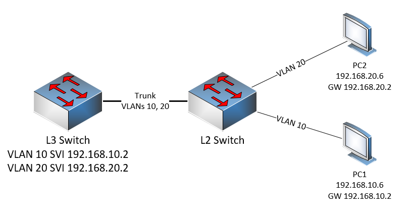
L3
Vlan 10, Interface Vlan 10 - 192.168.10.2/24
Vlan 20, Interface Vlan 20 - 192.168.20.2/24
Trunk between L2 and L3 switch
IP routing is enabled
L2
Vlan 10, interface vlan 10 no IP address
Vlan 20, interface vlan 20 no IP address
Truck between L2 and L3 switch
Pc in vlan 10
Pc in vlan 20
Pc (192.168.10.6) on vlan 10 with the default gateway pointing to 192.168.10.2
Pc (192.168.20.5) on vlan 20 with the default gateway pointing to 192.168.20.2
So the L2 switch doesn’t need any SVIs or IP addresses configured, you simply configure the correct ports on the correct VLANs. You create a trunk with both VLANs, and you create both VLANs on the L3 switch as well. At the L3 switch you create two SVIs, one for each VLAN that will act as the default gateways for each subnet/VLAN.
The result is, when PC1 wants to communicate with PC2, the traffic will:
go to the L2 switch on VLAN 10
go through the trunk on VLAN 10
reach the VLAN 10 SVI on the L3 switch
be routed from VLAN 10 to VLAN 20
be sent out of the VLAN 20 SVI on the L3 switch
go through the trunk on VLAN 20
reach PC2 via the access port on VLAN 20
This is very similar to Router on a Stick, where instead of an L3 switch, you have a router with subinterfaces, one for each VLAN on the trunk.
So for the L2, you don’t need to configure SVIs with IP addresses. The only reason you would do this is to have access to the switch itself via the network for CLI access and configuration. But L2 switches with SVIs won’t route traffic between VLANs.
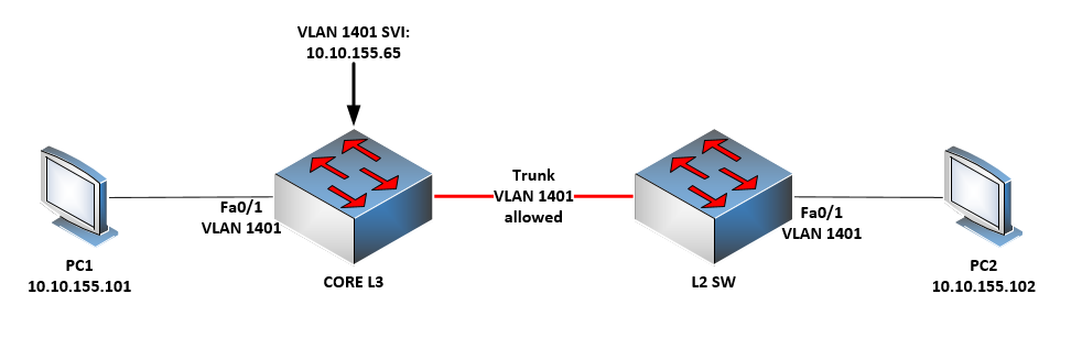
I’m trying to configure two PCs to be able to ping each other. After setup I’m unable to get them to ping each other.
Here is my setup, PC1 (..155.101) is directly connected to the core layer 3 switch. It’s port has been configured and placed into vlan 1401 with the following commands switchport access vlan 1401, switchport mode access.
PC2 (..155.102) is directly connected to a layer 2 switch. Also, It’s port has been configured and placed into vlan 1401 with the following commands switchport access vlan 1401, switchport mode access.
The Layer 3 switch houses the interface vlan 1401 and its SVI address is ..155.65. Between the two switches Vlan 1401 is allowed.
PC1 is able to ping the gateway ..155.65. Additionally, to ensure all is well I created a svi on the layer 2 switch and was able to ping PC2. The layer 3 switch is a 3750 and the layer 2 switch is a 3650.
The vlan has been allowed and has not been pruned in the configuration or either switch.
Now if Fa0/1 interfaces are configured as you state, and the trunk allows the 1401 VLAN, and the PCs are configured with these IP addresses, then they should communicate with each other. Just a note here, that no default gateway should be needed for this communication, since both PCs reside on the same VLAN and in the same subnet. No InterVLAN routing is taking place and thus, configuration of the SVIs is not necessary for connectivity.
Since PC1 can ping the SVI on the core L3 switch, and PC2 can ping the SVI on the L2 switch, then my attention would be brought to the trunk configuration. I suggest you follow this troubleshooting procedure:
Verify that VLAN 1401 has been created in both switches
Make sure that the VLAN 1401 SVIs in both switches are in the same subnet
Try to ping from one SVI to the other. If it fails examine the trunk configuration
attempt to achieve the same connectivity by changing the trunk link to an access link on VLAN 1401 and testing again
If you get the trunk or the access link working between switches, then your topology should function correctly. Let us know your results!
In this tutorial you use a line that, if you are having a multiples interface under Vlan use concept of SVI and if having a single interface under Vlan use concept of routed port ::
My question is here that if it is a routed port means switch port then why are you using word of Vlan for this routed port ?
Actually i am unable to get it why are we using SVI concept in this topic and suppose we use this then how can be make this useful for Inter-Vlan routing, could you emphasize it ?
I understand your confusion. The routed port is configured on Fa0/16 of SW3 and not on SW2. SW2 simply has the Fa0/16 port configured as an access port on VLAN 10, via which all of the hosts in VLAN 10 can reach the default gateway, which is the Fa0/16 port on SW3. Note here that, unlike the previous examples in this lesson, SW2 is a Layer 2 switch, and cannot be configured with a routed port.
The diagram is a little bit misleading because it shows that VLAN 10 of SW2 is only on the ports connected to the hosts, but VLAN 10 is also assigned to the Fa0/16 interface of SW2.
InterVLAN routing will allow hosts connected to access ports on a switch in one VLAN to communicate with hosts on access ports in another VLAN. The SVIs, which are virtual interfaces, act as the router ports between which routing takes place.
Dear Related team of network lessons!
Hello
I didn’t understand truly in Mr. Rene’s tutorial the usage of (SIV Autosate exclude command) would you please simply explain it to me that what is the usage of this command?
Thanks in advance for your help and support in this regard.
In order for an SVI to be active (line status up, protocol up), the VLAN that the SVI corresponds to must exist, and there must be at least one access or trunk port that is using the VLAN. Sometimes, you want the SVI to ignore the state of a particular port when deciding to be up or down. So if you issue the autostate exclude command on any interface, the state of that interface will not affect the state of the SVI.
So let’s say you have VLAN 10 SVI configured, and you have Fa0/1 and Fa0/2 on VLAN 10. If you enable both Fa0/1 and 0/2 and they are up/up, then the SVI will also be up. If you shut down Fa0/1, the SVI will still be up because Fa0/2 is on VLAN 10 and it is still up.
However, if you use the autostate exclude command on Fa0/2, then the state of this interface will not be examined to determine if the SVI must be up or down. So in this case, if you shutdown Fa0/1, the SVI will go down as well, even though Fa0/2 does exist on VLAN 10 and is still up.
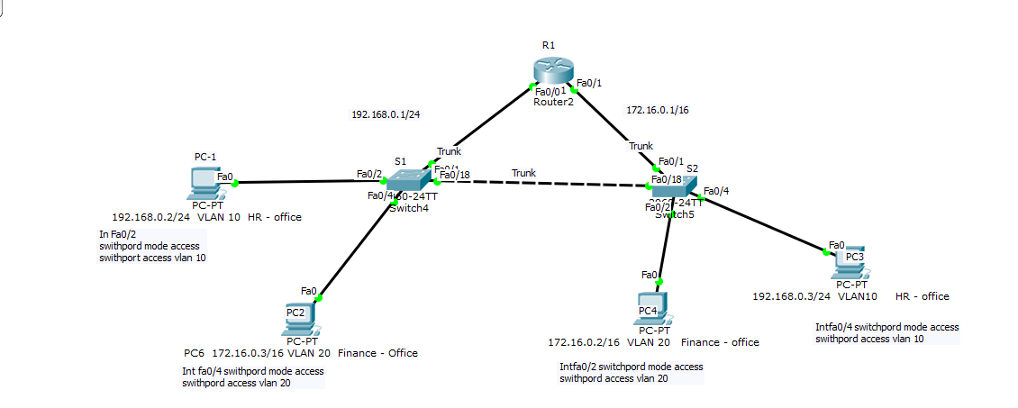
Dear Laz Sir one more question,
please see my scenario on each interface of router I have an access switch.
The question is here that I can ping from on router’s switch the other side of route’s switch only same vlan but I can’t ping those different vlans, so what should I do in order to create link between my different vlan on each side of router’s interface
Thank you in advance for the help and support in this regard.
Based on the addresses that are written in the diagram, the two switches are functioning at layer 2, and all routing is taking place at the router. There is no InterVLAN routing taking place on an L3 switch.
Since you can’t ping from one subnet to the other, I suggest you first verify that the hosts have the IP address of the router as the gateway (each subnet for itself) and make sure that all the hosts can ping their gateway.
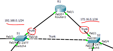
Secondly, why do you have a trunks configured between the router and the switches? This would require a router on a stick configuration, but this would also require you to have multiple subinterfaces on the same VLAN, something that is not possible.
Notice that if you have a trunk on these interfaces, then you have two subinterfaces on each of the Fa0/0 and Fa0/1 interfaces, with a total of 4 subinterfaces. But you only have a single subnet appearing for each link.
I would suggest you don’t make these trunks, but make one of them function on VLAN 10 and the other on VLAN 20 and make those router interfaces function as the default gateway for each VLAN.
Try these things out and let us know how you get along!