Thanks sir,
Appreciated I received the response of my questions as each vlan equals to a subnet so on each parent interface of router I created to sub interface and set IP address and now both VLAN 10, and 20 have ping reply with each other on each interface side of router.
There are two types of switches: Layer 2 switches, which are capable only of switching, and Layer 3 switches, which can perform both switching and routing. If you use a Layer 2 switch, and you separate it into VLANs, in order for the VLANs to communicate with each other, they require the use of an external router. A Layer 3 switch however, is capable of what is called inter-VLAN routing, which essentially means that you can perform routing between the VLANs on the device itself.
You can find out more about this feature, how it works, and why it is useful at the following lesson:
hi ,
i have a question regarding router on stick .. the ip addresses assigned for each vlan in the sub interface should be different networks as you did ? or is it also ok if they are in the same network ?
thanks for the grest explanation !
A router by definition must have interfaces assigned with IP addresses that are on different subnets. If you try to assign two interfaces with addresses in the same subnet, you will get an error message. For example, if you try to assign 192.168.1.5 255.255.255.0 to FastEthernet 0/1 and 192.168.1.6 255.255.255.0 to FastEthernet 0/2 it won’t allow you to do the second command.
The same is true for subinterfaces. Subinterfaces are treated as physical interfaces as far as the assignment of IP addressing goes. So to answer your question, the router would not let you perform such a configuration.
If I understand correctly, you want two ASAs to provide connectivity to the same VLAN via at least one port on each ASA, and then to apply policies to this VLAN. In order to achieve this, you will have to connect the ASAs together, and enable switching (Layer 2) on these ports. That way the same VLAN can span both firewalls.
But then there’s a problem. The devices on this VLAN will all require the same default gateway. This must be an SVI interface on one of the two ASAs. If you configure one ASA to do this, then the other ASA is simply functioning as a switch, and you’re not using any of its firewall capabilities.
In order to correctly configure such a scenario, you must use the failover feature of the ASA. You can set up an Active/Standby failover, which is described in the following lesson:
or, you can apply an Active/Active failover, about which you can find out more at this post.
In any case, what the failover feature provides is two ASA devices that will, from the point of view of the hosts in the subnet, function as a single device. In the active/active scenario, the two devices will actually share the load of the traffic and the implementation of the policies.
Once the failover is set up, you can then apply any policies you like, but you have to ensure that the same policies are implemented in both devices in the same way, so you have consistent behaviour.
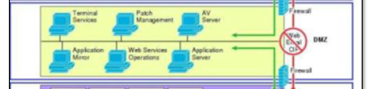
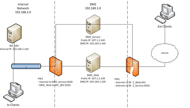
FW1 is connected to the internet, the DMZ, and the internal network
FW2 is connected to the DMZ network (outside interface), and the internal network (inside interface)
Internal Network is 192.168.1.0 255.255.0.0
DMZ Network is 192.169.1.0 255.255.0.0
DMZ machines have two NICs, one connected to FW1 and one connected to FW2. The NICs connected to FW2 have static IPs in the 192.169.1.0 range. The NICs connected to FW1 have static IPs that are publicly accessible from the internet.
The Machines on the DMZ are connected to both the FWs using Dual NICs
Can the Machines in the DMZ be on the same VLAN but two different Subnets as depicted ??
How this Networking is different from the Active/Standby Config you have Mentioned ?
There are a couple of issues with this setup. First of all, any traffic between the internal network and the Internet seems to be going via one of the two servers. You state that FW1 is attached to the internal network as well but I don’t see that on the diagram, so I’m not sure what is happening there.
The servers in the DMZ can have two NICs and each NIC is in a different subnet, and yes, that is acceptable. But again, are these servers being used to route traffic? I guess the ultimate question is what is it that you want to achieve? By answering this question, we can then move on to look at the topology necessary to achieve that.
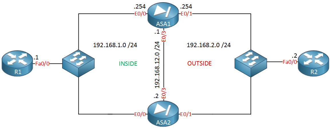
The Active/Standby or Active/Active scenarios use a topology like this:
R1 is a host on the inside network while R2 represents a device on the Internet. Here the two ASAs function similarly to two routers usingHSRP. As far as the host is concerned, there is only one ASA, because the two devices function logically as a single device. If you want to add a DMZ, you can add another switch and connect it to both ASAs.
So your scenario would not work with active/standby or active/active, because the two servers actually use different subnets for each NIC, whereas in the scenario I am describing, the ASAs are viewed as a single logical device, meaning a single subnet must be used.
If you want to find out more about these Active/Standby and Active/Active scenarios, take a look at the links I shared in the previous post.
1)For the case inter-vlan using SVI Concept, Is their no need to assign ports either in access mode or trunk mode like router on stick method?
2) For SVI case, Is only mentioned configuration enough b/c you did not configure any
trunking and encapsulation
3) For SVI case, communication will be happen b/w vlans on the basis alike directly connected n/w automatically make place in routing- table and reachable to each other, is that concept we are using here?
4) For Routed port case, first of all why are we using it here b/c f0/1,f0/2 and f0/16 are in
same vlan so that they are reachable to each other and second thing why are we we
not using f0/16 as trunk port and encapsulation and same on sw3 alike we did on
router using router on stick method?
5) if we use two vlans both assigned to different interface alike router on stick method and we use layer 3 switch on other end instead of router then we have to do same configuration for this method and this will also be called router on stick method?
No, because the only interfaces you need to configure are the SVIs. In the router on a stick scenario, you have a physical port on the switch and another on the router, that both had to be configured appropriately. Here all of that has been replace with two SVI ports.
Yes, this configuration is enough. You don’t need trunks and encapsulation any longer because you’re not using a separate switch and router with subinterfaces. This means you no longer have the physical link between these devices which requires these types of configs. There is no trunk in the SVI case.
Yes, exactly.
The scenario here is different. Fa0/1 and 0/2 and 0/16 on SW2 are all on the same VLAN, and yes you are right, they can all already communicate with each other. However, what is being described here is the fact that SW3 can have its Fa0/16 port configured as a routed port so that it can act as a router to allow H1 and H2 to reach the network that is “Somewhere… far far away”.
Yes, if you wanted to you could duplicate the router on a stick method using the topology found in the routed port scenario, but this is not something that you should ever do in a production network.
when yu want to communicate between different vlans, you need a router ..because they are not the same subnet
i also learnt that the trunk link between switches will help to carry multiple vlan info
so why not use the trunk link
why go for inter vlan routing
You are correct that in order to transmit traffic from one VLAN to another, you must route that traffic through a router.
A trunk however does something different. A trunk is a link between two switches that allows you to carry traffic of two or more VLANs. It’s kind of like a highway with multiple lanes, where the frames are sent along separate lines. But, frames cannot change lanes in the trunk!
So a trunk will carry traffic of multiple VLANs, but it will not allow the traffic of one VLAN to go to another VLAN. The traffic still remains separate. Only a router can route traffic from one VLAN to another.
Take a look at this lesson for more information on trunks:
and at this lesson for more info on inter-VLAN routing:
I have a question regarding a type of port. Can the port on the layer 2 switch be a trunk port when connecting to a routed port on a layer 3. I see in your example its an access port but that only carries 1 vlan. What if I had multiple vlans i wanted to carry over. Would this then be a case for using an SVI instead?
On a Layer 2 switch, you can create SVIs, however, their only purpose is to gain access to the CLI of the switch. You would use the IP address of the SVI as the destination of an SSH or Telnet session. An SVI on a Layer 2 switch would not be able to perform any routing.
It is possible to connect a trunk port on an L2 switch to a port on a router, which is operating at Layer 3. However, in order to achieve this, you must configure what is known as “Router on a Stick”. This is where you configure subinterfaces on the port on the router that each correspond to a particular VLAN on the trunk port of the switch. More information about this can be found here:
In the example in this particular lesson, port Fa0/3 on SW1 which is connected to R1 is actually a trunk port.
Note that all of the above assumes that you are using an L2 switch. If you use an L3 switch, then everything changes, and you can configure things as shown in section 2 of the lesson.
Hello Dear Team of Network lessons,
I did not understand purpose of autostate exclude command in layer3 switch.
Can you please clearly as an example explained to me.
Hi, i was wondering why the inter vlan routing is not included in the new CCNP course, if I was wrong, please refer me to the link as i could not find it under switching.
Hello,
I have not used gns3 in a long time and never was able to install a layer 3 switch, but now I have been able to do so, but when I connected one to a router, they cannot even ping directly connected interfaces. I have vlan 10 on esw with ip 10.0.0.2/24 vlan access mode on port 2, port 2 connected to router fa0/1 with ip 10.0.0.1/24. vlan is created in esw. it is shown in "show vlan-switch. it is spanning tree forwarding. I can see the devices in show cdp neighbor on both sides. But…still cannot ping from one device to other device, router cannot ping 10.0.0.2 and switch cannot ping 10.0.0.1 on router. What am I missing? Routing is turned on. Thanks.