good analysis Abhishek
AD of 9 or FD of 9 to R1? As u say before the 5 was reported by R4 to R3 right? And now R3 has AD value of 5 through R4 and FD value of 9 via R4 right? So the FD 9 will share to R1 right and that would comes as the AD vale for R1 to reach destination network via R3 right? Can u confirm the above u mentioned is AD of FD of 9?
Hello Unni
Yes, you are correct, I used the incorrect term. The mention of Advertised Distance (AD) and Feasible Distance (FD) have to do with perspective. From the point of view of R4, the FD to the destination is 5, and the AD from R3 is 9. From the point of view of R3, the FD is 9, and the AD from R1 (for example) to the destination is 12.
I hope this has been helpful!
Laz
Hi Laz,
In EIGRP introduction tutorial, I think the AD value advertised by R3 to R1 should be 9 instead of 12( how could you say 12 ) and in return AD advertised by R1 to R3( If advertisements possible b/w neighbors it must be FD to reach Destination) is 12 don’t understandable, why R1 advertise (FD or AD=12) to R3 , you has not mentioned anywhere the neighbors will advertise the AD and FD to each other if this is possible then R4 advertise Ad=9 to R3 and in return R3 will advertise same to R4 ?
Hello Pradyumna
Yes you are correct, it should be 9, that is a typo. I will let Rene know to change it.
Thanks!
Laz
1 Like
Minor typo for you:
If you lose the successor because of a link failure EIGRP will copy/paste the feasible successor in the routing table
If you lose the successor because of a link failure EIGRP will copy/paste the feasible successor into the routing table
1 Like
Hi Matthew
Thanks for catching that, I’ll let Rene know.
Laz
Hi Rene/Laz,
Couple of questions. There must be 5 K values to determine the metric of EIGRP path namely Bandwidth, load, reliability, delay and MTU. Although as explained in lesson we only use K1- BW and K3 -Delay to calculate the Metric, why wasn’t MTU not mentioned/considered anymore along with other K values?
- Lets assume we have 3 possible paths to reach the destination from the source router, out of these 3 paths assume 1 will become successor and the other path will become feasible successor, but there is also another 3rd path to the destination, my question is that the topology table supposed to have all possible paths to the destination or not? irrespective of a path being successor/ feasible successor or neither but not just successor and feasible successor is this assumption right?
Thanks and Regards,
Teja
Hello Teja
By default, EIGRP uses only the K1 and K3 coefficients, and the rest are set to 0. This is done because this is considered to be optimal for most networks. However, it is possible to enable the use of the other coefficients in the metric calculation. Now you may often read that the K5 coefficient is not used to calculate the metric. But it’s in the formula, isn’t it? What do they mean it’s not used?
Well, take a look at the formula again, this time separated into its constituent parts with coloured boxes:
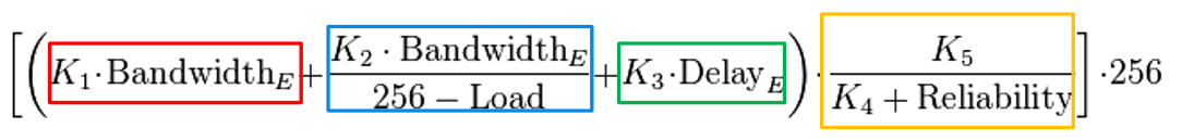
Notice that each K coefficient is related in some way to a corresponding value of some sort.
For example:
- K1, which deals with bandwidth, is actually multiplied by the bandwidth
- K2, which deals with load, is also multiplied by bandwidth, but is related to load
- K3, which deals with delay is multiplied by delay
- K4 which deals with reliability, is added to the reliability value
But K5, doesn’t have a corresponding MTU value to be multiplied with. Now this is the important part. The MTU of a particular path is actually advertised within EIGRP routing updates, however, that value does not appear in the formula! Only the coefficient K5 does.
And actually, the K5 coefficient appears only as a part of the reliability quotient. So in essence, even if K4 is not zero, K5 must also be “not zero” in order for reliability to be involved in the calculation.
So why is K5 there? Well, if it is set to 1, then of course reliability will be included in the metric, but it also plays another role that has to do with load balancing. It is used when equal-cost paths for the same destination exceed the number of allowed paths set using the maximum-paths command. For example, we set maximum allowed paths for load balancing to 5 and the metric calculates 6 equal-cost paths for a single destination. In this situation path with the lowest MTU will be ignored.
Using the show ip eigrp topology all-links command, you will be able to display all the entries in the EIGRP topology table including non-feasible-successor routes. If you don’t use the all-links keyword, only the successors and feasible successors will appear. You can find out more about this command at the following command reference:
I hope this has been helpful!
Laz
1 Like
Hi Laz,
Thank you very much.
Regards,
Teja
I am a CCNP qualified and preparing to renew my cert but I have never understood feasible distance and you explained it so simply. Kudos
1 Like
Thanks Rene, that was very helpful to me to understand better EIGRP operation!
1 Like
I am not able to visualize this …from the perspective of r3 r1 and r2 are directly connected so why is there an advertised distance ..was able to understand before this topology now it’s confusing can you kindly help me out
Hello Kevin
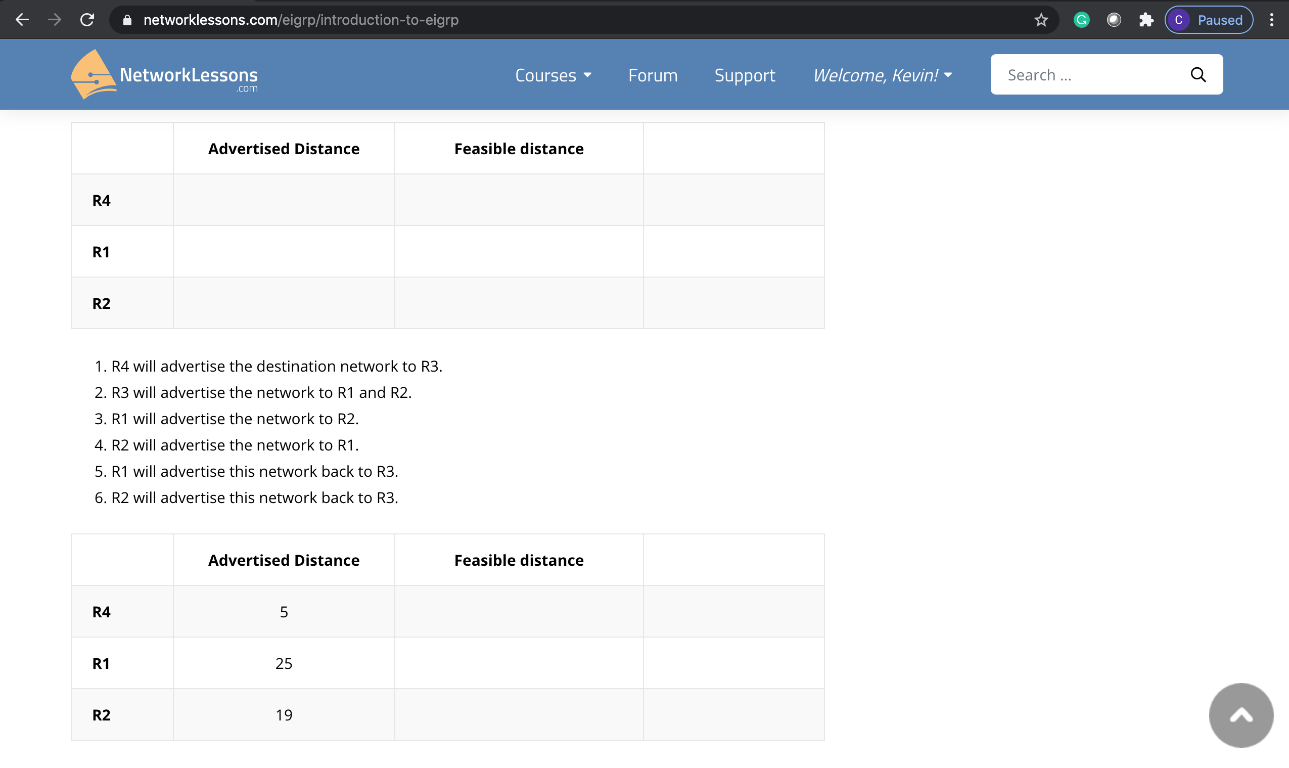
You must remember that the exercise is taking place with the following in mind:
- The process is being viewed from the point of view of R3.
- The destination network whose distance is being measured is the network designated Destination connected to R4.
Now the advertised distance to the destination is the distance that the other routers (R1, R2, R4) have to that destination network. The other routers report this distance to R3, and R3 creates a table listing those distances.
So R4 tells R3 that its distance to the destination network is 5, as seen in the following diagram:
R2 will report to R3 that it has a distance to the destination network of 19 as shown in the diagram below:
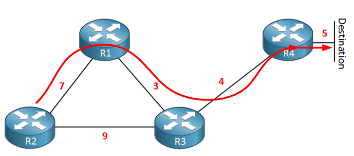
And R1 will report to R3 that it has a distance to the destination network of 25 as shown below:
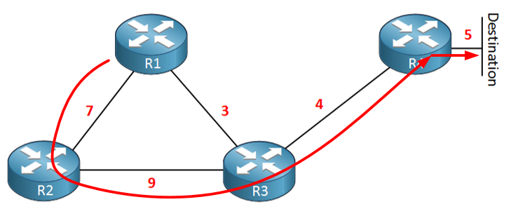
Now, why does R1 report the distance going through R2 to get to the destination? And why does R2 report the distance going through R1 to get to the destination? Well, that’s because of the split-horizon rule. Never report routing information to a destination to a neighbor via the same interface you learned about that network from.
So you see, it doesn’t matter that the other routers are directly connected. The advertised distance has to do with the destination network in question.
I hope this has been helpful!
Laz
Need some clarification on why 28 was the FD in the lesson. Searched the forum but did not see a specific answer. Thanks
The light bulb just clicked on while doing the lesson again. The value of the directly connected link makes it 28. Thanks.
Hello Donald
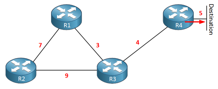
We’re looking at this particular topology:
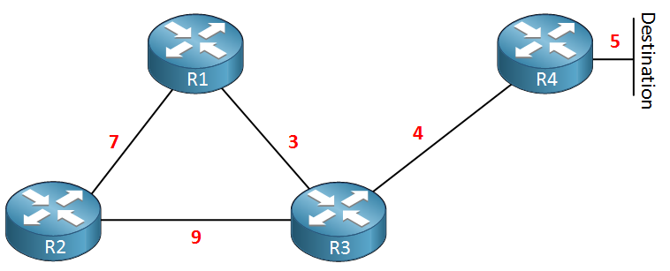
And from the point of view of R3, we are looking at the following advertised and feasible distances to the destination:
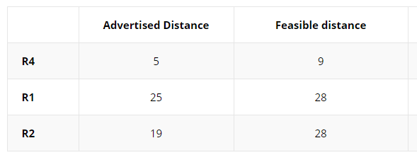
When R3 learns the advertised distance of each router, in order to get the feasible distance, it simply adds the distance between itself and the particular router. For example:
- R3 has an advertised distance to the destination of 5 given by R4. Add to this the distance between R3 and R4 (4) and you get 5+4=9.
- R3 has an advertised distance to the destination of 25 given by R1. Add to this the distance between R3 and R1 (3) and you get 25+3=28.
- R3 has an advertised distance to the destination of 19 given by R2. Add to this the distance between R3 and R2 (9) and you get 19+9=28.
I hope this has been helpful!
Laz
I completed a lab in CML with the same topology as before one difference would be that I did not change the metric on any of the interfaces. What I am seeing is that R1 is routing to R3 to connect to the loopback on R4. R2 is routing too R3 to get to the loopback on R4. From my understanding would the path to the loopback from R1 be R1->R2->R3->R4 based on the lesson? What am I not understanding here?
Hello Alan
If you have not changed any of the default metrics in your topology, and all of the links are of the same type, then the routing that you describe is correct. From R1 and R2, in order to reach the loopback on R4 you would have the following routing:
- R1 → R3 → R4
- R2 → R3 → R4
In the lesson, Rene used different metrics for the links between the routers to help in explaining the advertised distance and the feasible distance.
In particular, the lesson doesn’t say that the route to the loopback on R4 should be via R2. What it does say, however, is that from the point of view of R3, the advertised distance from R1 to R4 is 25 and this is measured via R2. This is because the distance to the destination that R1 advertises to R3 cannot be via R3. It has to be via a different route. (It’s hard to get your head around it, I know… ![]() ).
).
I hope this has been helpful!
Laz
1 Like
Laz,
Your sentence “This is because the distance to the destination that R1 advertises to R3 cannot be via R3. It has to be via a different route.” For some reason or another gave me the light bulb moment I was searching for I think. Just to verify, this is happening due to split-horizon since R3 is advertising to R1 and R2, they cannot respond back through the same interface in which the original advertisement came from. In this example if all the metrics were the same lets go with 2. The advertised distance from R1 to R4 would be 8 from R3 perspective still?
Thank you,
Alan