A crossover cable is used whenever the devices to be connected are the same (or when connecting a PC directly to a router). But this is the case only for Ethernet connections using RJ-45 connectors and UTP cable. This is not the case for serial connections or fiber connections of any type.
The concept of crossover cables only applies to copper UTP cables with RJ-45 connectors on an Ethernet link.
So if you have routers on both ends, and you require RJ-45 connectors for Ethernet, then a crossover cable should be used. It doesn’t matter if you are connecting to the Internet or to some internal network.
You seem to have replied to me in a private message. I will post it here for the benefit of other readers as well. You responded:
Hi Lagapides
Thanks for info but I want to know it’s practical implementation of crossover cable connected between the router and confirm me is the ethernet port in router can be used for wan link to service provider .You said that same device at end have use cross over cable but this cabling is used for ethernet connection.This statment is contradict .Please share in more deep as I m beginner in networking and confused to associate cable in gns 3 or packet tracer.
Why the statement is contradict that we use cross cable if device at both end is router as I know router is used for wan purpose or to communicate to other network for providing internet connection by choosing best path from routing table
We only use serial cable at serial port for wan connection and ethernet port of router is used to connect lan part .by connected straight cable.
Please tell me in ds what a router behave if we use cross cable .
Thanks & Regards
Shivam Chahal
I understand your confusion. First of all, let’s take a look at the definition of a WAN. A WAN is a type of network that connects the local network in a building or campus to either the Internet, a private network connecting remote sites, or to a network maintained by an ISP. The technology used by that WAN can be anything. It can be Ethernet (Metro Ethernet), serial, fiber optic, microwave link, xDSL, Cable modem, ISDN, MPLS, or others. A WAN link can use many different types of technologies, but what makes it a WAN is the geographic scope. In general, a WAN will connect a local network to the outside world, or to remote sites.
Secondly, a router is not limited to functioning only as a device connected to a WAN. Routers can exist within the enterprise network of a building or campus, and route traffic between internal subnets.
So you can have routers that do not connect to the WAN as well as routers that connect to the WAN. In both cases, many different types of technologies can be used for connectivity. WANs are not limited to serial connections and LANs are not limited to UTP based Ethernet cables. So you may have a crossover cable connect two routers inside your local network, or you might have a router connected to the WAN using an a crossover cable as well. Or you may have fiber optics within your network interconnecting many routers or a fiber connection providing you connectivity to the Internet or to remote sites.
In the past, WAN meant serial, and LAN meant Ethernet. This is no longer the case as many of these technologies, especially Ethernet, have been developed for use on the WAN as well.
Could you please tell me in brief is the switch which contain ethernet ports have its own mac address means many ports have individual mac address or we consider the overall mac address .As i read your post in that we only discuss about the mac address of host only for which switch make entry and take decision whether they have entry of mac of destination host or not .
Also tell me what above the change in port of router regarding mac address .
This is an excellent question. A Cisco switch has a unique MAC address, which is the MAC address of the switch as a whole. This is called the base MAC address. Each port on the switch also has a unique MAC address as well.
The base MAC address is used for things like STP, so it can take part in root bridge elections for example. You can see the base MAC address in the output of the show version command:
Switch#show version
Cisco Internetwork Operating System Software
IOS (tm) C2950 Software (C2950-I6Q4L2-M), Version 12.1(22)EA4, RELEASE SOFTWARE(fc1)
Copyright (c) 1986-2005 by cisco Systems, Inc.
Compiled Wed 18-May-05 22:31 by jharirba
Image text-base: 0x80010000, data-base: 0x80562000

!<-- Output Omitted -->

63488K bytes of flash-simulated non-volatile configuration memory.
Base ethernet MAC Address: 0060.5CCE.1135
Motherboard assembly number: 73-5781-09

!<-- Output Omitted -->
Now if you do a show interface for each interface on the switch, you will see a different MAC address for each of the interfaces like so:
Switch#show interfaces
FastEthernet0/1 is down, line protocol is down (disabled)
Hardware is Lance, address is 0050.0f16.2d60 (bia 0050.0f16.2d60)
BW 100000 Kbit, DLY 1000 usec,
reliability 255/255, txload 1/255, rxload 1/255

!<-- Output Omitted -->
Each MAC of each port will be unique. These MAC addresses are used as source and destination MACs for data sent to and from the switch itself using that port.
Now it is important to note here that a switch’s MAC address is not used at all for transient traffic. Transient traffic is traffic that traverses the switch, but neither its source nor its destination is the switch itself. It is traffic sourced from one host to another, and the switch just switches it based on the destination MAC.
For this reason, the MAC addresses of the switch never appear in the MAC address table. This is often confusing for networking trainees. The MAC address table contains the MAC addresses of hosts that use the switch for traversing traffic.
Thanks for responding but i want to know more in detail about the below statement as the point is not clear , my question what internal mechanism switch do that they hide its individual port mac address to communicate Host A to Host B .
Any command and scenerio to verify that the mac address of port is
not used during transient traffic .
Kindly share in brief description .
Regards
Shivam Chahal
Each MAC of each port will be unique. These MAC addresses are used as source and destination MACs for data sent to and from the switch itself using that port.
Now it is important to note here that a switch’s MAC address is not used at all for transient traffic
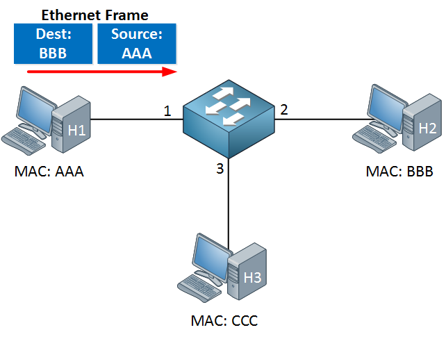
Here we have H1 sending a frame to H2. Notice the destination MAC address in the Ethernet frame is BBB, and the source MAC address is AAA. There is no MAC address of the switch itself in the frame being sent. H1 and H2 don’t need to know the MAC address of the switch ports they are connected to in order to communicate with each other. After H2 responds, the switch builds up its MAC address table, showing which ports correspond with which host MAC addresses.
The switch will build the MAC address table like so:
Port 1 MAC AAA
Port 2 MAC BBB
Port 3 < blank >
Port 3 is blank because H3 has not yet sent or received any frames.
You can see here that the MAC address table contains the MAC addresses of the hosts connected to its ports and not the MAC addresses of its own ports. So for transient traffic, meaning traffic through the switch from one connected host to another, the MAC addresses of the switch don’t play any role at all.
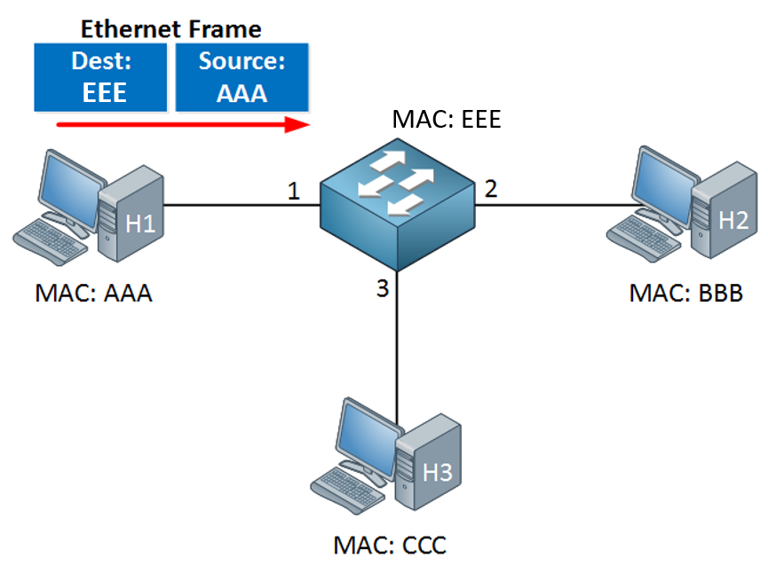
Now if I have traffic with a destination of the switch itself, then the MAC addresses would be involved. Let’s say H1 is the computer of the network administrator, and he wants to connect to the CLI of the switch. Let’s also say that the MAC address of the switch is EEE. Then we would have the following:
Hi Rene ,
I want to know from you as my doubt still not clear as your recent post i understand the point that for transient traffic switch does not used its interface mac address nor its base mac address .
Base mac address used for STP purpose for selecting root bridge . if i am wrong then correct me . Do needful in clarifying below points :
I want to know where individual interface mac address is used , Could you please share with header illustrated way , as in previous post you mentioned if we want to access switch CLI then you use base mac address EEEE as in figure not the interface mac address , why it so happen ? Still you don’t describe the point of using individual port mac address of switch with diagram . Please share in header format . strong text Doubt 2: As initially switch mac table is empty then how they recognized that particalur destination mac which i want to transmit a frame is connected to which port . How they identify the device of mac .
*Doubt 3: If i don’t know the destination mac , then what switches behave to transmit the frame . Doubt 4: As i know Arp is used in Layer 2 , is they work here or not ? If yes then how ? Doubt 5:
How a switch behave if it act as a L3 , and how it work in details ?
Team , request you to clear above points as i invested days and time , but not getting satisfactory answer .
This depends on the interface of the switch you connect to. For example, to connect to a switch CLI through VTY (telnet or SSH) you could use these options:
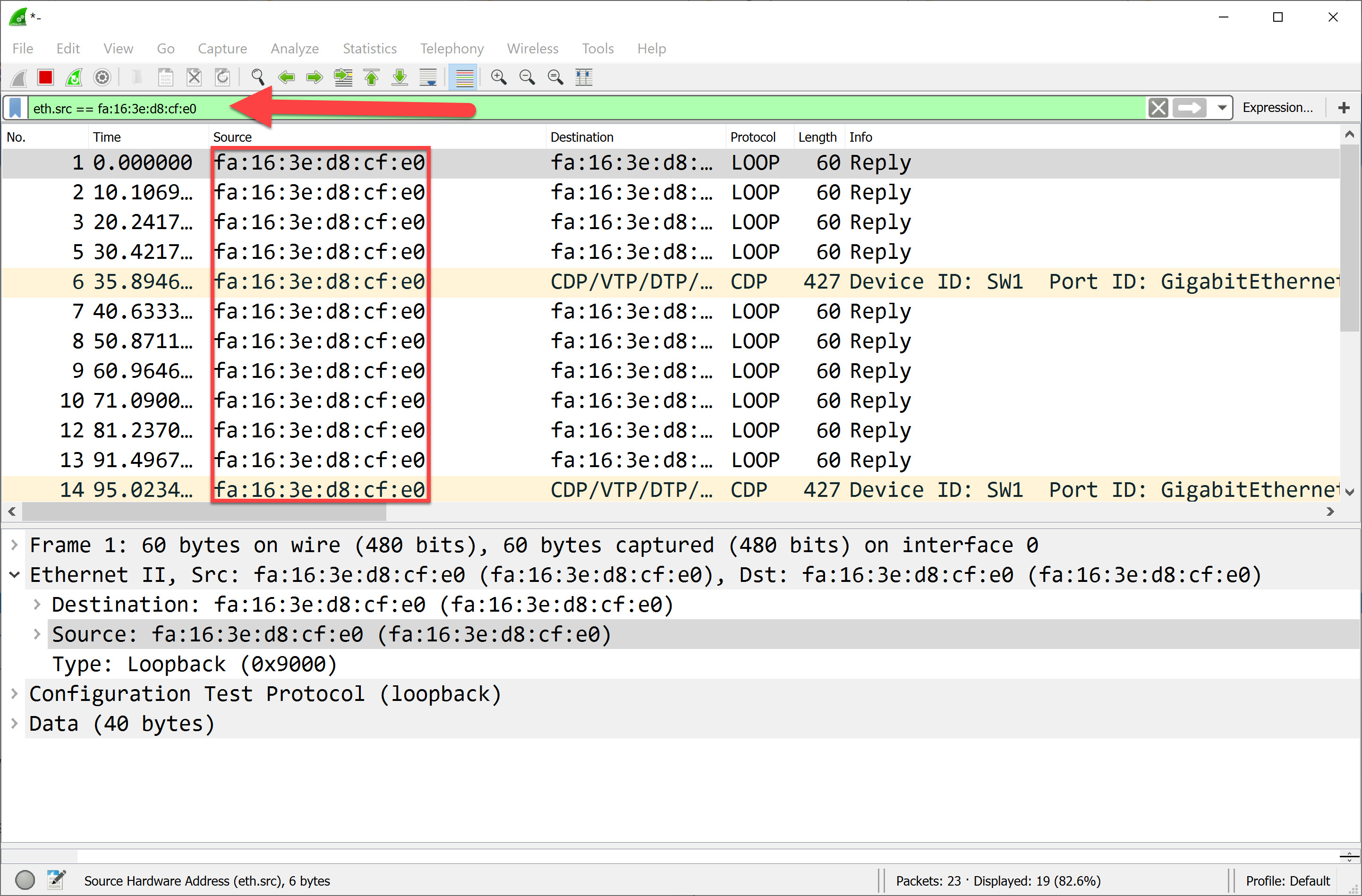
CDP is an example, and you see some loopback traffic. There are more protocols though.
A switch learns the source MAC address of incoming Ethernet frames, that’s it. When the switch forwards an Ethernet frame, it looks at the destination. When there is a match, it forwards it on the correct interface. If there is no match, it floods it on all interfaces except the interface where we receive the frame on. That’s all the switch does. Nothing more.
If you have two devices connected to a switch, and you just powered everything on then the first Ethernet frame that a switch sees is probably an ARP request. This allows the switch to learn the source MAC of device 1. When device 2 answers with an ARP reply, it will learn the MAC address of device 2.
They flood it on all interfaces except the interface where you receive the frame on:
ARP is used whenever a device has to map an L3 IP address to an L2 MAC address. For “switching”, the switch doesn’t need this. It only processes L2 frames.
When you connect to a switch using telnet or SSH, the switch uses ARP as well. It needs to map a L3 IP address to a L2 MAC address. Here’s its ARP table of my last example:
SW1#show ip arp 192.168.12.1
Protocol  Address          Age (min)  Hardware Addr   Type   Interface
Internet  192.168.12.1           20   fa16.3e1f.457a  ARPA   GigabitEthernet0/1
A switch will “switch” only between L2 interfaces. If you add the no switchport command on an interface then it becomes an L3 interface. You can add an IP address on a L3 interface, and the switch can route traffic between L3 interfaces.
Here is an explanation of the difference between routers and switches:
And here a detailed example of how traffic moves through L3 interfaces:
I have general question , as above Statement , i want to know , within an enterprise or lan N/W , we uses router to route internal traffic ,suppose R strong text1 and R 2 are connected at Ethernet port via Crossover cable , is it pass Ethernet frame or packet while passed it routes .
As i know if I use Gig Ethernet port its use ip address then it will behave as a L 3 or somehow if they are L 2 Port then it don t take ip address and passed Ethernet frame
I think if R 1 and R 2 used in WAN via crossover cable then it will behave as a L 3 because NW is different and we can give ip address to gig Port as well and i if i want to behave router connected within its private network through crossover cable then we can used as a L 2 Port where frame can be transverse . Is they automatically choose l 2 Port when we connect router within LAN through crossover cable please confirm .
Kindly correct my statement if i am wrong here .
I think it’s important to understand specific definitions of various concepts here. Remember that routers are devices that communicate on Layer 3. This means that all of their ports are assigned IP addresses regardless of the type of port used (serial, Ethernet, fiber, copper, wireless etc), and routers perform routing between subnets connected to each of their ports. The functionality at Layer 3 is independent of the connection technology, and of whether you consider the connection a WAN or a LAN.
That which determines if L2 or L3 is used, is the type of device. Router = L3, Switch = L2.
Whether the router will function on L2 or L3 does not depend on the cable used. This is the beauty of the OSI model. The underlying layers (crossover cable = physical layer, Ethernet = data link layer) have no effect on what happens at Layer 3 (IP). Remember, pure routers will always function at Layer 3.
I think the problem here is that some manufacturers create devices with a “WAN port” and several “LAN Ports” and they define the WAN port as routed, and the LAN ports as switched. This is unfortunate, because they give the wrong impression. WAN does not always mean routed (L3) and LAN does not always mean switched (L2). You must separate these concepts in your mind.
For example, you can have a WAN using Metro Ethernet, which gives you Layer 2 connectivity, but it is a WAN. So you must separate the thought that WAN is somehow associated with routing and LAN with switching.
So, to summarize
router will always function at L3 regardless of connection type.
WAN and LAN designate the geographical scope of a network and not the Layer on which a port will function
Although some technologies are associated with WANs and LANs, these do not dictate the Layer on which a device will function.
I understood your point , my last question as i am doing some basic configuration on cisco router in my organization , while assigning ip to Ethernet port in config mode , it will assign on some port easily , while some of port not assigned the ip , is there any concept of vlan tagging here to assign ip address .
Could you please help in this ,as in above statement you mentioned that we can assigned ip address in all interface whether it is serial or Ethernet port .
Case updated :-
Please need your kind intervene here as i m accessing a Cisco router , while checking its interface by doing sh ip interface brief i found that on some Ethernet port device use particular vlan and use a IP Address as a default gateway for connecting LAN .As i directly enter ip address on free interface it show error and reflect it is an L2 Port , could u please share the reason , why it so happen and how can we find it ?
And in what scenario we can assign vlan on cisco router ?
Any output command then please share
The truth is that I did mention that in routers, all ports will have an IP address and function at Layer 3. But there are some exceptions.
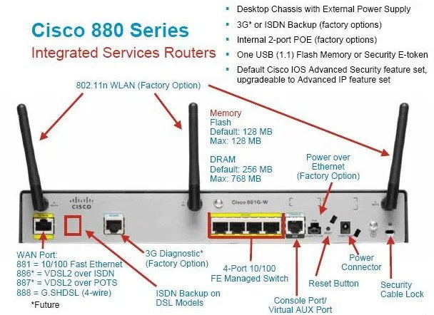
There are some low end Cisco devices such as the 800 series routers for example, that have an “integrated switch”. These devices are like a router and a switch stuck together in one device. You can see the ports of a Cisco 880 router in the following diagram:
The four ports called “4-Port 10/100 FE Managed Switch” is a section of the device that can be configured only as switch ports. Specifically, these are only Layer 2 and cannot be assigned IP addresses. They can however be all assigned to the same VLAN, and you can create an SVI with an IP address, and then use all four, where the devices connected to the would have a default gateway of the IP address of the SVI.
Now this device also has what is called a WAN port, which is indeed Layer 3. But it doesn’t have to be connected to the “WAN”, it can be connected to your internal network. It is simply a Layer 3 port. But it also has a wireless port (as it is a wireless router) which is also Layer 3, and a port that connects to a 3G network, which is also an L3 port. So this router can route traffic between four subnets, each using a different technology: the wireless network, the 3G network, the “WAN port” and the SVI of the switch.
Strictly speaking, this device is a combination of a router and a switch and an access point all in one, but for simplicity, Cisco calls it a “router”.
It all depends on what device you are using. If it is an 800 series, you cannot make a physical port a Layer 3 port. If it is another series of devices, like a L3 switch, then you can convert the port to a Layer 3 port by using the command no switchport. But it all depends on the platform.
To support team of network lessons.com!
Dear Sirs,
I didn’t understand in your website’s tutorial truly that what pairs or colors of UTP or STP cable are using for send of data and what Paris or colors of it are using for receiving of data!
if someone briefly or short explain me that what pairs of STP or UTP cable are using for send of data and what pair of it are using for receiving of data?
I thank you and appreciate in advance from you help in this regard.
Regards,
Ajmal “Ahmadi
Network lessons.com member, from Afghanistan
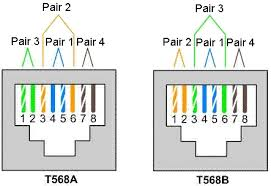
First of all, there are two ways to terminate an RJ-45 connector. Using the EIA/TIA-568A and EIA/TIA-568B termination. The only difference between the two is how the colours of the wires are ordered. The following image shows these terminations:
On the images, you can see the pins being numbered from 1 to 8. Regardless of the colours being used, the pins that are used for data transfer are as follows:
For Ethernet (10 Mbps) and FastEthernet (100Mbps),
on one end of the link, pins 1 and 2 are used to send data and pins 3 and 6 are used to receive.
on the other end, pins 1 and 2 are used to receive data and pins 3 and 6 are used to send.
Note that a pair of wires is used together, as if it is a single conductor. Which switch will use which pins is automatically adjusted using the auto MDIX feature.
GigabitEthernet on the other hand doesn’t use specific pins for specific direction of traffic. All four pairs are used for traffic in both directions. Even so, the correct pins for each stream of data must be used on each end. For this reason the auto MDIX feature is also employed here.