Sir, one more question that I didn’t know!
I understood that on one end of the link, pin 1 and 2 are used to send data and pins 3 and 6 are used to receive data, up to here I understood but what about the remain pins 4,5,8 and 7 , for what are used as in cross over and straight through all the four pairs which equals to totally eight wires are used in RJ45!
Thanks for your help and support in advance.
Pins 4, 5, 7 and 8 are not used for Ethernet (10 Mbps) and FastEthernet (100 Mbps), but are used for GigabitEthernet and 10G Ethernet. This is the same for both straight through and crossover cables.
Remember that in modern switches, for all types of Ethernet, because of auto MDIX, either a straight through or crossover cable can be used. The devices will electronically decide which pins will be used for sending and receiving.
Power over Ethernet (PoE) can use the unused pairs of wires (for 10 and 100Mbps Ethernet) for sending DC current to power for PoE devices, but the technology is not limited to just using those wires. As you can see from the PoE lesson below, both power and data can be sent over the same pairs of wires without any problem.
So to answer your specific question, those unused pairs are simply not used for 10 and 100 Mbps Ethernet.
Hello Sir,
First of all thanks for response to my question, after your explanation regarding the pins in RJ-45 one question created in my mind and I have concern regarding that to know.
As you mentioned that pins 1 and 2 are used to send data and pin 3 and 6 are used to receive data, to explain my question or concern simply to you if I discuss from the view point of colors!
Pin 1 = white Green and pin 2 = Green
Pin 3 = White orange and Pin 6 = Orange
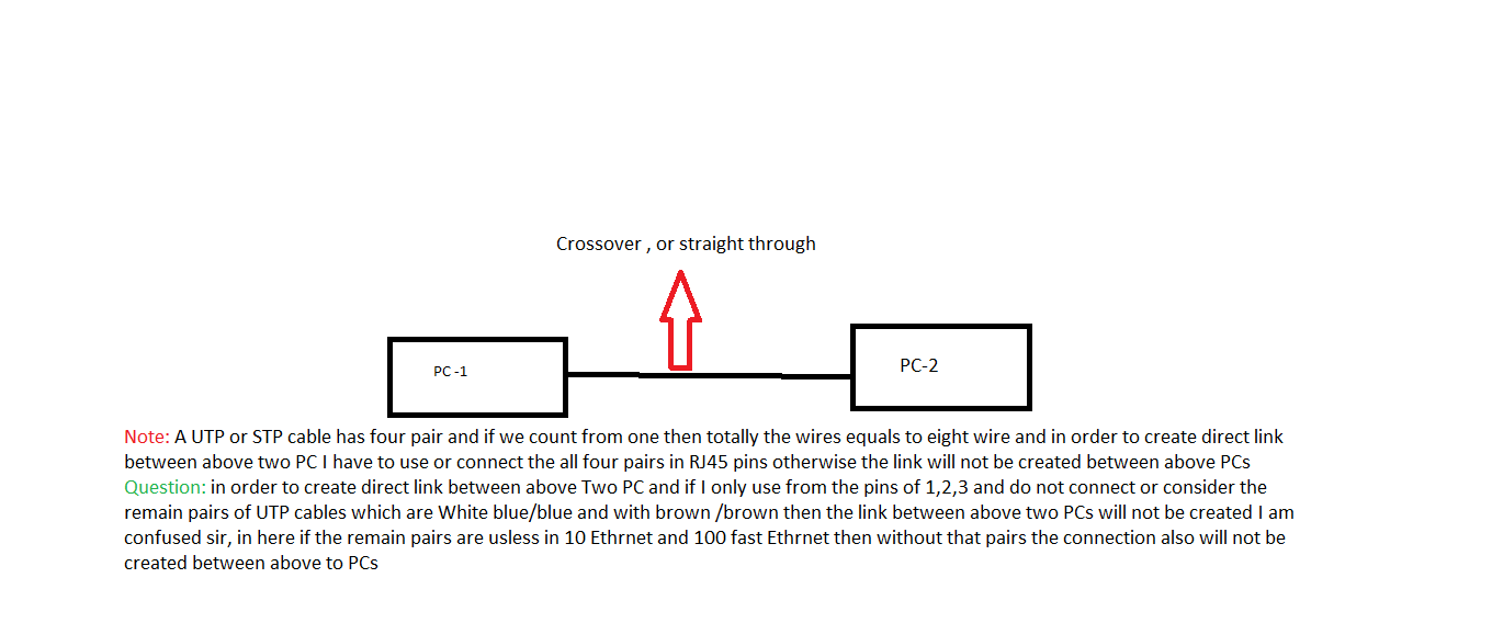
Note: please see the attached scenario I want to create link between two PC through UTP cable directly without any switch and if drop and do not connect the remain pairs of UTP cables in pin of RJ45 then the connection will not be created between two PC, Please see in attached my scenario
I thank you and appreciate in advance from your help and support in this regard.
The quick and short answer here is, you need a crossover cable to connect PCs like this.
In general, if the device is the same (PC to PC, Switch to Switch, Router to Router) then you need a crossover cable. If the device is different (PC to switch, switch to router) then you need a straight-through cable. The only exception to these rules is PC to router, where you need a crossover cable once again.
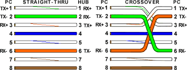
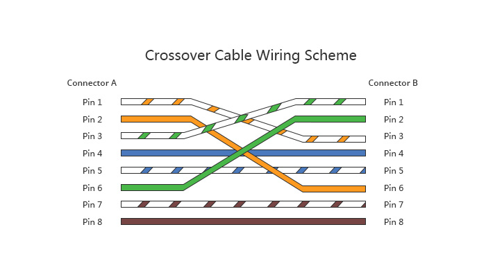
The reason the crossover is needed is because for both PCs, pins 1 and 2 are transmitting pins, and 3 and 6 are receiving pins. So it only makes sense that:
pins 1 and 2 on PC1 (Tx) connect to pins 3 and 6 on PC2 (Rx)
pins 1 and 2 on PC2 (Tx) connect to pins 3 and 6 on PC1 (Rx)
It may help to trace out these paths on the crossover cable diagram above.
The same logic goes for routers and switches too. However, almost all modern networking equipment employ what is called auto-MDIX, which automatically detects and changes the roles of the Tx and Rx pins so that communication can take place.
Hi,
why do we need this LLC header and why don’t we need it for all Ethernet Frames? Do we need it just for Ethernet 802.3 Frames where we use the lenght field and don’t know the upper layer protocol? I can see PID: CDP in the LLC layer.
The quick answer: The use of the LLC depends on which Ethernet standard is being used. Ethernet has two standards: IEEE 802.3 and Ethernet II. The first uses LLC while the second does not.
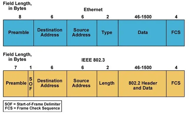
The detailed answer: The main difference between IEEE 802.3 and Ethernet II is the definition of the two-byte field that comes right after the source MAC address.
This is the Type field for Ethernet II and the Length field for IEEE 802.3. It is the value found in this field that will determine which type of Ethernet you are using.
Type field = contains a value that indicates what Layer 3 protocol is being used. For example, a hex value of 0x0800 indicates IPv4 and 0x86DD indicates IPv6. Used by Ethernet II
Length field = contains the length of the frame in bytes, with a maximum value of 1500 bytes. Used by IEEE802.3
For values greater than or equal to 1536, the frame must be an Ethernet II frame, while for values less than or equal to 1500, the frame must be an IEEE802.3 Ethernet frame. (Values from 1501 to 1535 are undefined). When standardizing Ethernet, both standards were acceptable, and can coexist on the same network, and are differentiated in this way.
Now when using IEEE802.3, the recipient still needs to know how to interpret the frame. So this standard required an IEEE802.2 (LLC) header to include the type of Layer 3 protocol being used.
Today IP networks use Ethernet II, simply because the field after the Source MAC address must contain the IPv4 or IPv6 type value. So in most cases, LLC will exist only for Layer 3 protocols other than IPv4 and IPv6.
I was looking for these terms and to relate any cisco device . I have gone through few google links and youtube . Suppose a switch is having 24 ports both 1G/10G SFP , will each port have individual PHY or a common PHY for all port . Want to know these terms , functions and relate to device .
The MII, PHY, MDI components of connectivity described in the video are those used for all Ethernet implementations including fiber and copper. The PHY component is typically found within the switch electronics in the form of a set of chips. Depending on the device model and the speed of the particular port, you can have a single PHY chip be shared across multiple ports, or have a single chip per port, or in some cases (as is the case with a 100Gbps interface of a Cisco ASR 9000), two chips per interface. It all depends on the architecture of that particular device.
Cisco’s documentation for high end devices (such as the 9600 series for example) does include information about how the PHY components are laid out.
Few more questions i am trying to find out is " Q1 . Along with ASICS why we need a separate external CPU ?" .
My current understanding is :
ASIC is a piece of silicon which is uses multiple engines(programmable like UADP or non-programmable) with a fixed pipeline manner . If its non-programmable we can add a FPGA and programme it as per our requirement . Its function is to forward packets based on engines on the defined pipe line to other ports . Most of the things like packet processing ASIC has done what is the requirement of another component cpu in network hardware ? can you please give a example of packets forwarding path .
Q2 : Is ASIC works on dataplane and CPU works on control plane ?
There are actually two types of crossover cables. A Half-crossed cable and a fully-crossed cable.
The Half-crossed cable is the more common one, which crosses over pins 1, 2, 3 and 6 as shown in the lesson. This cable was designed to be used with FastEthernet (100Mbps) which uses only four out of the eight wires (two to transmit, two to receive). So there was only a need of crossing over the “active pairs” so to speak.
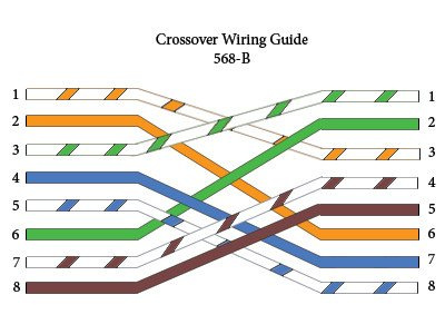
GigabitEthernet uses all four pairs (four to transmit, four to receive). For GigabitEthernet devices that don’t use audo-MDIX, a fully crossed cable must be used. This cable crosses all eight wires. So in addition to 1, 2, 3, and 6 of the half-crossed cable:
pin 4 on one end is crossed to pin 7 on the other
pin 5 on one end is crossed to pin 8 on the other
pin 7 on one end is crossed to pin 4 on the other
pin 8 on one end is crossed to pin 5 on the other
The result is a fully crossed cable, which looks something like this:
The whole reason for using crossover cables is because the pins on the ports of different devices are in a different order. This order is defined by what is known as the Medium Dependant Interface (MDI) type. The two types are:
MDI, which requires pins 1 and 2 as Tx, and 3 and 6 as Rx
MDI-X which requires pins 1 and 2 as Rx, and 3 and 6 as Tx
Now routers and end devices (PCs, IP phones, IP cameras etc) use MDI, while switches and hubs use MDI-X. Whenever you connect two devices of the same MDI type, you need a crossover cable. Whenever you connect an MDI device to an MDI-X device, you need a straight through cable.
Now switches, even Layer 3 switches, are still MDI-X devices, so even if you connect a L3 switch to a router, you will still use a straight through cable. The cable to use only depends on the hardware, and not on whether or not you are using an L2 port or an L3 port on a switch.
Having said all of this, all modern network devices use Auto-MDI-X which automatically detects whats on the other end, and logically switches the pinouts automatically, so there is no need for a crossover cable.
Is there any scenario in the modern day when we’d need to care about crossover vs straight-through cables when it comes to connecting devices? As it seems all networking devices these days auto-detect the pin configuration in the ethernet cables.
The truth is that today, it is rare that you will need to use a crossover cable. I can only remember one situation several years back, where we had to use a crossover cable because another feature needed to have the auto-MDIX disabled on the interface. (I think it had to do with using link aggregation between a Cisco and a non-Cisco device). For this reason, we needed to use a crossover cable.
Unless you come across some obscure situation that deals with various vendors, strange uses of network features, or simply very old equipment, you probably will not come across the need to use a crossover cable.
Question. I recently attempted to configure a new ASR1001 and bring up BGP with my ISP neighbor. BGP state is IDLE and the 10Gbps interface with SFP+ is in UP DOWN state.
I assume BGP is idle because the interface is in UP DOWN.
I know with ethernet connections (in my case using single-mode fiber between 10Gbps interfaces on my end and the ISP end), mismatched negotiation can cause UP DOWN. But I thought with SFP’s you cant set speed and duplex. Am I incorrect about this?
When BGP state is in IDLE, it is almost always because of a lack of network connectivity to the BGP peer. See the BGP Neighbor Adjacency States lesson. In your case, having the interface up line protocol down is indeed the culprit.
When does this happen? Especially on an SFP fiber connection? It’s not the duplex and speed settings, like it would be for copper-based connections, since you can’t set that on an SFP connector. It has two fibers, one for Tx and one for Rx, and thus is always full duplex, and the SFPs are made for a specific type of fiber standard, which includes the speed.
But it could be a number of other things including dirty connectors on the SFP or a bad fiber cable or connector somewhere along the path. These things can cause just enough errors to corrupt frames being sent causing a line protocol down. It could also be an incorrect SFP transceiver on the other end of the link, or the use of an incorrect fiber patch cord, like using Single Mode fiber instead of multi-mode or visa versa.
The Administrative and Operational modes give us information about how the particular port is configured. Specifically:
Administrative Mode indicates what we actually configure on that particular port. For example, Trunk or Access or LaGP or PaGP or ON etc…
Operational Mode is the mode with which the port behaves in response to the configuration done onto a particular port, and its negotiation (if any) with the port on the other side of the link.
For example, if we connect two switches together and leave them in their default states, then the administrative mode would be dynamic auto, since by default, dynamic auto is enabled. That’s what they are configured with. But the operation mode will be static access, because the result of the negotiation is to have the ports be in access mode.
You can find out more information about this at the following lesson: