Thank you Lagapides.
I understand now. Thanks
1 Like
@lagapidis
I had few queries related to optics & their usage. Can you please help me with scenarios here.
- Multimode SFP on both ends & cable is single mode. Will communication work?
- Single Mode SFP on both ends & cable is multimode. Will communication work?
- If one end has Single Mode SFP & other end has Multimode SFP & cable is multimode? will it work?
- If one end has Single Mode SFP & other end has Multimode SFP & cable is Single mode. will it work ?
Hello Tejas
As a general rule, when using fiber optics, the cable and SFPs used on both ends should be of the same type. This is the only way to guarantee that a fiber link will be functional. So if you’re using a multimode cable, make sure both SFPs support multimode. Also, if you are using structured cabling, make sure the optical patch cords you are using also match the type of optical cable in the structured cabling.
You must also keep in mind that there are several types of multimode cable including 50/125 and 62.5/125. (These numbers describe the diameter of the core and the cladding in microns). You must ensure you are using the same type of cable as different cable types can cause refraction at the connector which results in corrupted frames.
Now having said that, I have come across situations where Multimode SFPs are used with single-mode fiber or visa versa, or a situation where the structured cabling is multimode and the patch cord is single-mode, and they seem to have worked. Nevertheless, is no guarantee that a particular combination will work. Such configurations are prone to errors and corrupted frames and should never be used in a production network. Also keep in mind that some SFPs can support both multimode or single mode cabling, so take a look at the specs to ensure you’re using an SFP that supports your cable type.
One thing that will definately not work is to use a single mode SFP on one end and a multimode SFP on the other. These would not be able to talk to each other. And actually if you do, there is a chance you could damage the transcievers, which can sometimes be quite expensive. ![]()
I hope this has been helpful!
Laz
How many types of Ethernet frame out there , I have heard many times, Can u explain it ?.
Ethernet II
IEEE 802.3
IEEE 802.2 LLC
IEEE 802.2 SNAP
What is LLC and SNAP used for ?
Hello Narad
The truth is that Ethernet has three different formats. All of those things you mention have to do with the format of the Ethernet header, and what information it contains.
Remember the OSI model? Ethernet “lives” in the Data Link layer. The Data Link layer is separated into two sublayers. The upper sublayer is called the Logical Link Control or LLC, while the lower sublayer is called the Media Access Control or MAC.
Now the three formats essentially determine what is contained within the Ethernet header.
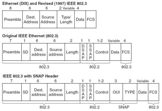
- The IEEE 802.3 defines the part of the header that is included in this lesson. This is also known as Ethernet II. This is the most commonly used Ethernet.
- In addition to 802.3 IEEE 802.2 is added as an additional section to the header, which exists within the LLC sublayer.
- Thirdly, you can have the use of 802.2 including what are known as subnetwork access protocol (SNAP) extensions that add mechanisms for multiplexing on networks using 802.2.
These formats use different frame types and different MTUYs but can coexist on the same physical medium. The following image shows the difference in the headers of these types of ethernet frames and the fields that correspond to each standard.
I hope this has been helpful!
Laz
1 Like
@lagapidis i have a doubt on frame size ,
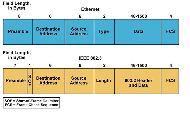
in ETH II , the total frame size including all is 8+6+6+2+1500+4=1526
in 802.3 , The total frame size including all is 7+1+6+6+2+1500+4=1526
But from which prospective you said that “For values greater than or equal to 1536, the frame must be an Ethernet II frame, while for values less than or equal to 1500, the frame must be an IEEE802.3 Ethernet frame. (Values from 1501 to 1535 are undefined). When standardizing Ethernet, both standards were acceptable, and can coexist on the same network, and are differentiated in this way.”
Hello Narad
My statement concerning the values has to do with the values contained within the Length/Type field.
Both Ethernet II and IEEE802.3 frames can coexist on the same network. How does a device know to interpret a frame as Ethernet II or as IEEE 802.3? By the value in the Length/Type field.
If that value is 1500 or less, it is a Length field, thus it is interpreted as an IEEE 802.3 frame. (The length field indicates only the size of the payload without the header). If that value is above 1536, then it is a Type field, and the frame is interpreted as Ethernet II.
I hope this has been helpful!
Laz
Hi
Can you prepare a specific lesson about fiber optic types?
Thanks
Hello Giovanni
You can make a suggestion for a lesson at the Member Ideas page below. You may find that others have made similar suggestions, and you can add your voice to theirs as well.
In the meantime, I can tell you some information about fiber optics here. There are two major types, multi mode and single mode.
Multi mode fiber optics:
- has a larger core diameter, > 10 micrometers
- for shorter distances typically between 500 and 2000 meters
- used within buildings primarily
- cheaper
- can be either graded index or step index fiber
Single mode fiber optics
- smaller core diameter of less than 10 micrometers
- for longer distances of up to 100 km
- used within buildings as well as inter-building and inter-campus communication
- more expensive
The following link to a diagram shows the various ways in which light travels through these types of fiber.
I hope this has been helpful!
Laz
Hi thanks for your reply.
I mean a lesson that explain the color standards, connectors..speed ,the dwdm , dark fiber and all this stuff.
But for sure i will ask it in the lesson ideas .
Thank you
Hello Giovanni
Go ahead and make the suggestion. In the meantime, let me give you some more information.
Fiber optic cables are typically colour coded to indicate the type of cables used. For patch cords, the cable jacket, as well as the connector, have specific colours to indicate the type of cable. For cables with multiple fibers in them, a colourful bundle of tubes can be seen. Each colour provides an identification of each fiber to correctly connect them on both ends, but also to ensure that techs will perform the splicing as the cable has been designed. More info about the colours used can be found at the Fiber Optic Association’s website below:
As for connectors, there are a multitude out there for various purposes. The most common are LC, due to their compact size, but you will also find some FC and ST due to the fact that they lock in place, as well as SC, which can be found on slightly older equipment. Cisco devices using SFPs will use LC, while some older GBIC connectors will use SC. These are the connectors you will see 99% of the time in telecom, however, a detailed list of many types of connectors can be found here:
For Ethernet, speeds up to 10 Gb/s can be achieved with both fiber and UTP cable. The main advantage of fiber was distance. However, for speeds of 40, 100, and 400 Gb/s and beyond, only fiber optics can achieve such speeds. Currently, 100 Gb/s is a common speed that is achievable via fiber optics. The IEEE is currently working on TerabitEthernet technologies that are expected to reach 800 Gb/s and 1.6 Tb/s by 2023, all, of course, supported with fiber optic cables, reaching about 500 meters with multi-mode fiber, and well over 10 km with single-mode fiber.
Some more info about fiber can be found at this post as well:
I hope this has been helpful!
Laz
1 Like

hi why destination comes first in data link layer ? source should come first ?
Hello Abdul
Actually, the destination MAC address comes first, and there is a good reason for this. Switches will forward frames in one of two ways:
You can click on each of those to find out more details about them. Cut-through switching is the default on most modern switches. As the frame enters the switch, as soon as the destination MAC address is read, the frame is forwarded out of the appropriate exit interface without waiting to receive the whole frame.
By making the destination field appear first in the header, the frame can be forwarded sooner, and thus a higher throughput is achieved.
I hope this has been helpful!
Laz
A post was merged into an existing topic: ARP (Address Resolution Protocol) explained
Two separate questions on this chapter:
-
In Gigabit Ethernet, it uses four pair to send and receive, how does the PoE work over this since there isn’t a pair open for PoE? How can you send and receive over a pair that PoE is being pushed out?
-
How do Vendors keep from running out of MAC addresses? Do they reuse MACs after a period of time? I am sure some have to had cycled through.
Hello James
The answer is that both PoE and data are being sent over the same pairs of wires at the same time. This can be done due to the nature of the way PoE sends power, and the nature of the encoded bits on the wire.
PoE transmits DC power to devices by maintaining a constant voltage across the wire pairs over time. Conversely, data signals cause variations in the voltage across the wires. Due to these distinct characteristics, it is possible to transmit both power and data over the same pair of wires and separate them at the receiving end. Upon receiving the signal at the destination, one can “subtract” the voltage level provided by the PoE to obtain the original data signal.
There are 2^48 possible MAC addresses which is about 281 trillion. This number is considered enough to cover the current and foreseeable future of networked devices. If vendors adhere to the allocation and assignment rules set by the Institute of Electrical and Electronics Engineers (IEEE), then there is no concern about MAC address exhaustion.
Vendors like Cisco for example, may have multiple OUIs assigned to them, where each OUI delivers a set of 2^24 or over 16.7 million MAC addresses. There are also 2^24 possible OUIs and so far, about 30,000 have been assigned. So there are MANY more OUIs still available that can be assigned without the fear of running out of MACs.
I hope this has been helpful!
Laz