Introduction to MPLS

Hello Rahul

In its most basic form, the difference between MPLS Layer 2 and Layer 3 VPNs is that in Layer 2, you are provided with a flat MPLS topology where no routing takes place in the ISP’s network, while in a Layer 3 VPN over MPLS, the ISP actually participates in the routing of packets.

In more detail, Layer 3 VPN over MPLS, the service provider will participate in routing with the customer. The customer will run OSPF, EIGRP, BGP or any other routing protocol with the service provider, and these routes can be shared with other sites of the customer. Additionally, routing information from one customer is completely separated from other customers and tunneled over the service provider MPLS network. More information on MPLS Layer 3 VPN can be found here:

Layer 2 VPN over MPLS is more properly known as MPLS Layer 2 Virtual Private LAN service or MPLS VPLS. This technology essentially combines MPLS and Ethernet. This is a flat topology where Layer 2 services are provided to customers. Any routing that needs to take place will be done on customer devices connected to the ISP circuits. The limitation of this technology is that it is not as scalable as L3 VPN MPLS, due to the fact that it cannot have the same hirarchical structure that L3 provides. A little bit about VPLS can be found in this lesson:

I hope this has been helpful!

Laz

Hi Rene,

I am confused about MPLS that whether is it a Site-to-Site VPN or Remote Access VPN?

Regards
Varun

Hello Varun

When referring to MPLS, we usually don’t categorize VPN types such as site to site or remote access. However, if I were to choose one, then MPLS more closely resembles a site to site VPN. MPLS is not used to connect end users to a remote network like a common VPN may do, but it is used to connect branch offices and remote sites together.

Rene further describes this in the following post:

I hope this has been helpful!

Laz

Thanks alot Laz.

Regards
Varun

1 Like

Hi Rene ,

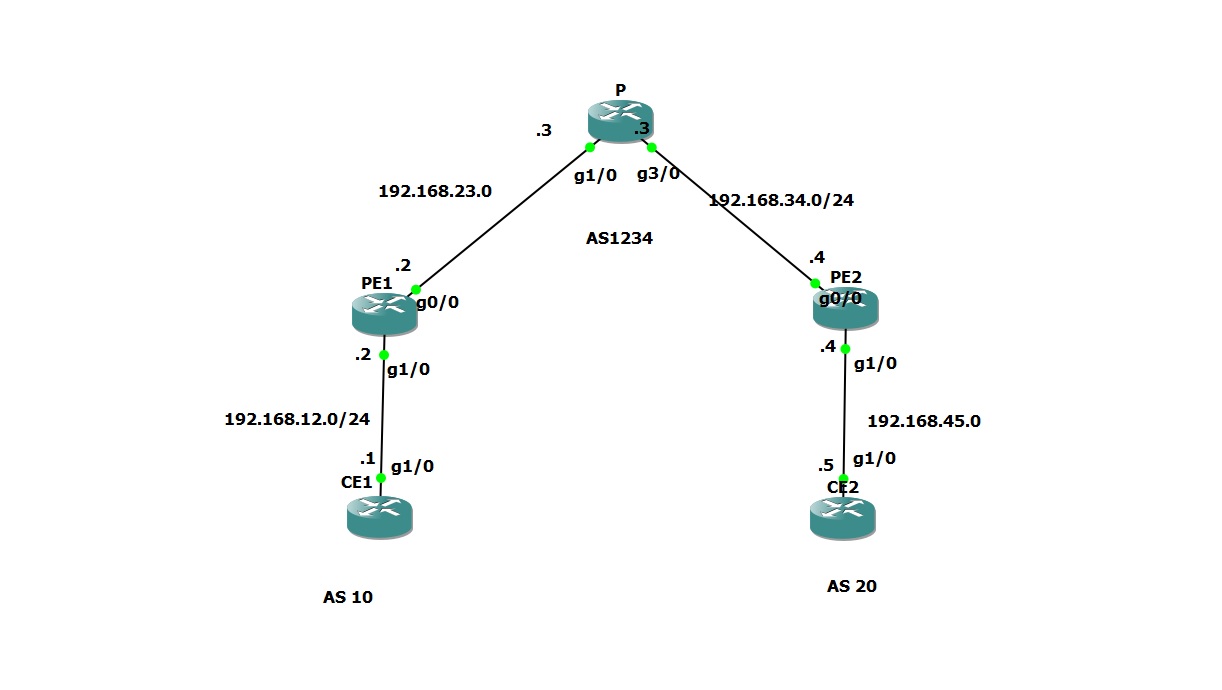
I am trying this lab , but IBGP peer using tunnel interfaces is not coming up and i am unable to ping from CE1 to CE2 . Can you please help .

show commands outputs configs attached :

PE1#sho ip route
Codes: C - connected, S - static, R - RIP, M - mobile, B - BGP
       D - EIGRP, EX - EIGRP external, O - OSPF, IA - OSPF inter area
       N1 - OSPF NSSA external type 1, N2 - OSPF NSSA external type 2
       E1 - OSPF external type 1, E2 - OSPF external type 2
       i - IS-IS, su - IS-IS summary, L1 - IS-IS level-1, L2 - IS-IS level-2
       ia - IS-IS inter area, * - candidate default, U - per-user static route
       o - ODR, P - periodic downloaded static route

Gateway of last resort is not set

C    192.168.12.0/24 is directly connected, GigabitEthernet1/0
     1.0.0.0/32 is subnetted, 1 subnets
B       1.1.1.1 [20/0] via 192.168.12.1, 00:08:06
     2.0.0.0/32 is subnetted, 1 subnets
C       2.2.2.2 is directly connected, Loopback0
     3.0.0.0/32 is subnetted, 1 subnets
O       3.3.3.3 [110/2] via 192.168.23.3, 00:08:26, GigabitEthernet0/0
     4.0.0.0/32 is subnetted, 1 subnets
O       4.4.4.4 [110/3] via 192.168.23.3, 00:07:57, GigabitEthernet0/0
C    192.168.24.0/24 is directly connected, Tunnel0
C    192.168.23.0/24 is directly connected, GigabitEthernet0/0
O    192.168.34.0/24 [110/2] via 192.168.23.3, 00:08:07, GigabitEthernet0/0
PE1#

-

PE2#sho ip route
Codes: C - connected, S - static, R - RIP, M - mobile, B - BGP
       D - EIGRP, EX - EIGRP external, O - OSPF, IA - OSPF inter area
       N1 - OSPF NSSA external type 1, N2 - OSPF NSSA external type 2
       E1 - OSPF external type 1, E2 - OSPF external type 2
       i - IS-IS, su - IS-IS summary, L1 - IS-IS level-1, L2 - IS-IS level-2
       ia - IS-IS inter area, * - candidate default, U - per-user static route
       o - ODR, P - periodic downloaded static route

Gateway of last resort is not set

     2.0.0.0/32 is subnetted, 1 subnets
O       2.2.2.2 [110/3] via 192.168.34.3, 00:08:30, GigabitEthernet0/0
     3.0.0.0/32 is subnetted, 1 subnets
O       3.3.3.3 [110/2] via 192.168.34.3, 00:08:30, GigabitEthernet0/0
C    192.168.45.0/24 is directly connected, GigabitEthernet1/0
     4.0.0.0/32 is subnetted, 1 subnets
C       4.4.4.4 is directly connected, Loopback0
C    192.168.24.0/24 is directly connected, Tunnel0
     5.0.0.0/32 is subnetted, 1 subnets
B       5.5.5.5 [20/0] via 192.168.45.5, 00:08:18
O    192.168.23.0/24 [110/2] via 192.168.34.3, 00:08:30, GigabitEthernet0/0
C    192.168.34.0/24 is directly connected, GigabitEthernet0/0
PE2#
PE2#
PE2#

-

PE1#sho ip bgp sum
BGP router identifier 2.2.2.2, local AS number 1234
BGP table version is 2, main routing table version 2
1 network entries using 132 bytes of memory
1 path entries using 52 bytes of memory
2/1 BGP path/bestpath attribute entries using 296 bytes of memory
1 BGP AS-PATH entries using 24 bytes of memory
0 BGP route-map cache entries using 0 bytes of memory
0 BGP filter-list cache entries using 0 bytes of memory
BGP using 504 total bytes of memory
BGP activity 1/0 prefixes, 1/0 paths, scan interval 60 secs

Neighbor        V    AS MsgRcvd MsgSent   TblVer  InQ OutQ Up/Down  State/PfxRcd
192.168.12.1    4    10      12      11        2    0    0 00:09:43        1
192.168.23.3    4  1234       0       0        0    0    0 never    Active

-

PE2#sho ip bgp sum
BGP router identifier 4.4.4.4, local AS number 1234
BGP table version is 2, main routing table version 2
1 network entries using 132 bytes of memory
1 path entries using 52 bytes of memory
2/1 BGP path/bestpath attribute entries using 296 bytes of memory
1 BGP AS-PATH entries using 24 bytes of memory
0 BGP route-map cache entries using 0 bytes of memory
0 BGP filter-list cache entries using 0 bytes of memory
BGP using 504 total bytes of memory
BGP activity 1/0 prefixes, 1/0 paths, scan interval 60 secs

Neighbor        V    AS MsgRcvd MsgSent   TblVer  InQ OutQ Up/Down  State/PfxRcd
192.168.24.2    4  1234       0       0        0    0    0 never    Active
192.168.45.5    4    20      13      12        2    0    0 00:10:49        1
PE2#

-

Version details:
===============
PE1#sho versio
Cisco IOS Software, 7200 Software (C7200-ADVENTERPRISEK9-M), Version 12.4(20)T, RELEASE SOFTWARE (fc3)
Technical Support: http://www.cisco.com/techsupport
Copyright (c) 1986-2008 by Cisco Systems, Inc.
Compiled Fri 11-Jul-08 04:22 by prod_rel_team

ROM: ROMMON Emulation Microcode
BOOTLDR: 7200 Software (C7200-ADVENTERPRISEK9-M), Version 12.4(20)T, RELEASE SOFTWARE (fc3)

PE1 uptime is 16 minutes
System returned to ROM by unknown reload cause - suspect boot_data[BOOT_COUNT] 0x0, BOOT_COUNT 0, BOOTDATA 19
System image file is "tftp://255.255.255.255/unknown"

CE1.txt (1.9 KB)
CE2.txt (1.9 KB)
P.txt (1.8 KB)
PE1.txt (2.1 KB)
PE2.txt (2.1 KB)


Regards,
Sameer.

Hello Sameer

Glancing at your configurations, I see the following differences:

  1. Your P router is missing the mpls ip command on your GigabitEthernet1/0 and 3/0 interfaces.
  2. You are using interface IP addresses to create the BGP neighbors rather than the loopback addresses.

I see more differences, some of which may affect the result some of which may not. In any case, I suggest that you go through the lab once again, and put in the commands step by step as indicated in the lesson. As soon as you see a certain command not returning the expected results, check it out and troubleshoot the specific problem. If you can’t figure it out, let us know and we’ll help you.

In this way it’s easier for us to help you if you make your questions more specific.

I hope this has been helpful!

Laz

Hi, just a question about the thing you mentioned about BGP neighbor adjacency between the loopback interfaces - why would we need to configure a route-map that changes the next-hop IP to the IP address of the tunnel interface?

Hello Inon

We are creating a GRE tunnel between the PE1 and PE2 routers. If we use the IP addresses of the GRE tunnel interfaces as the addresses between which the BGP peering will take place, then all BGP updates and hellos will be exchanged between the two over the GRE tunnel. Also, next hop IP addresses, which belong to the tunnel endpoints, will cause all user traffic to go through the GRE tunnel. This is the desired behaviour.

However, it is best practice to create BGP peerings between loopback addresses and not addresses of physical interfaces. This is because physical interfaces may go down, and peerings would be lost, even if there are alternate routes available between the routers. So, what Rene is saying here is that it is possible to create the BGP peering between the routers using the loopback IP addresses.

If we do that, all BGP communication (hellos, updates etc) will be exchanged between the loopbacks OUTSIDE of the GRE tunnel. Such communications would not be encapsulated by GRE. But the problem is that next hop IP addresses would be those of the loopbacks and not the tunnel interfaces. This would cause all user traffic to also be sent between the routers OUTSIDE of the GRE tunnel, that is, unencapsulated. This is not what we want.

So if we wanted to use loopbacks as the BGP peering addresses, and we wanted user traffic to go over the GRE tunnel, then the solution would be to create a route map that would change the next hop IP address of all prefixes learned through BGP to the IP addresses of the tunnel interfaces. Then, BGP information can indeed be exchanged between the loopbacks, but the next hop IP addresses would be those of the tunnel interfaces, causing user traffic to go through the GRE tunnel, which is what we want.

I hope this has been helpful!

Laz

Hi
why we have to Configer BGP if we want to enable MPLS
can i enable MPLS without BGP?

Hello Ridhwan

Strictly speaking you don’t really need to enable BGP when using MPLS. You can configure it using IGPs as well. However, because MPLS is primarily a WAN technology that interconnects remote enterprise networks, as well as connects them to the Internet, the primary method of exchanging routes between such infrastructures is BGP. This is why you see MPLS paired up with BGP so often and in various types of scenarios.

I hope this has been helpful!

Laz

Hello Rene,
Are these topics available to us?

Hi Ankit,

Which topics did you mean?

Rene

Hi Rene and Laz,

From what I can remember about MPLS is that the labels are learned per prefix.
as you mentioned on the other LDP lesson - LDP won’t generate a label for routes learned via BGP, therefore they will be without any label tag.

in that case shouldn’t those prefixes get routed via IP routing instead of LSP? and in that case you must configure the “P” Core with iBGP and create a full mesh am I right?

the example is indeed valid for L3VPN which do encapsulate another label stack for each VRF Prefix automaticaly. (in juniper you have to specify this function statically and choose your own label, does it also posibble with Cisco?)

From some old labs i’ve done , I can remember that there hasn’t been any connectivity between those CE1-CE2 as in ur exmaple though, I hope you could clarify this subject more accurately to me because right now I can’t lab it.

Thanks you very much!

Hello Nitay

Yes, you could route those prefixes using IP routing rather than labels, however, that defeats the purpose of the MPLS network. MPLS will generate labels only for routes that are in the RIB that are not BGP prefixes. This means that the IGP that is being run between the CE and PE routers will generate labels. So labels are really only generated for customer prefixes. iBGP is then used to create neighbor relationships between PE routers so that the VPNv4 routes can be exchanged. The core of the ISP network need only run a routing protocol (independent of the CEs) to allow iBGP to function.

I’m not sure if this clarifies your inquiry, if not, please let me know.

I hope this has been helpful!

Laz

Thanks for your reply,

The VPNv4 routes are used for labels generated for L3 VPN over MPLS.

My intent was to understand my assumption:
CE1-PE1-P-PE2-CE2-NETWORK

PE1-PE2 - they have iBGP relationship
CE1-PE1 & CE2-PE2 - eBGP relationship

PE2 wouldn’t generate LABEL for the “NETWORK” that connects to CE2
Therefor PE2 wouldn’t exchange labels via LDP with “P” and “P” wouldn’t advertise those non-exist labels to PE1.

Therefor PE1 woulnd’t have any labels for the “NETWORK” but he sees PE2 as his next-hop.

the next-hop does generate a label but because we have MPLS core and the customers aren’t VPN customers, then I’m pretty sure that when CE1 trying to ping CE2 it wouldn’t tag any label.
Therefor “P” router will drop the ICMP because he doesn’t know how to route it.

Because you gave us the example in this lesson that CE1 does will make the ping to CE2, my question is 1)would the PE1 router make the routing via ip routing? or 2)would it use the PE2 next-hop label for the routing?

From what I remember the 2nd question is an invalid operation for the router because there would be a recursive lookup for CE2 via the PE2 next-hop

Hello Nitay

Actually, even though the P router doesn’t have any labels for the NETWORK, it will still be able to route information to 5.5.5.5 because it is not using the IP address to get to the destination, but MPLS labels.

If you take a look at Rene’s lesson at this point:

When CE1 pings 5.5.5.5, it is successful. First of all, CE1 has learned of this route via eBGP from PE1.

It is not using a label, as you correctly stated, but is using the routing table populated by eBGP. Now if you look at PE1, it has an entry for 5.5.5.5 in its routing table as well. Again, not as an MPLS label, as you correctly stated. The routing table states that the next hop is 4.4.4.4 which is the PE2 router. How does it get to 4.4.4.4? Well this is where MPLS kicks in. Taking a look at the MPLS forward table, you can see that 4.4.4.4 can be reached by adding label 17 to the IP packet and forwards the packet to the P router. This is where the MPLS header is added.

If you continue the lesson as it describes the traversal of the path from router to router, you will see that the P router will pop the label 17, and will send the packet to the next hop which is PE2.
This too is routing using labels.

The packet arrives at PE2 without any labels, just as a regular IP packet. At this point PE2 has the routing information for 5.5.5.5 via eBGP and sends the packet to CE2.

A similar procedure is explained for the return trip of the echo reply.

I hope this has been helpful!

Laz

Thanks for your help Laz,

I could double check today the procedure and it seems like the learned prefix through BGP wil be tagged with the same MPLS Label as the known prefix for the showed next-hop in the BGP table.

This mechanism is the same for 6PE where the same prefixes (both IPV4 & IPV6) are comupted in the LFIB to use the same label which means the same LSP for different prefixes.

in the 6PE case its also different IP protocol but in this case it is the same LSP for different prefixes which belong to the same IP protocol - I guess i coulnd’t figure that out neither accept it because it seems realy odd to me.

1 Like

Dear Network lessons,

Please help explain what is pseudowire and when I execute show mpls l2transport vc 100 detail how can I tell the preferred path is configured for pseudowire?

Thank you

Hi Kenneth,

I explain the pseudowire mechanism as a virtual ppp connection that operate like a gum.

both sides of the VPWS L2 VPN are sticked to the same virtual connection and the rest of the internet infrastructure are invisible, the pseudowire is like an overlay technique to make the connection over the MPLS network which act as the underlay connection between the sites.

in VPLS, that pseudowire is the same but acts more like a broadcast connection or P2MP instead of ppp like in VPWS.

when you issue the "show mpls l2transport vc 100 detail"command, you see the virtual pseudowire itself and not the actual underlay path that installed into the forwarding plane as in multihomed BGP where only 1 path installed as the main path.

each VC has its own LSP toward the pseudowire’s destination and the LSP itself derived through the underlay network configuration which is invisible to the pseudowire

Hello Kenneth

Just to add a bit to Nitay’s response, a pseudowire is a mechanism that allows you to connect two devices at Layer 2 over a Layer 3 network. It is like a tunnel that is created between two locations on the network where devices on the same subnet can communicate with each other. You can find out more about it at this lesson:

When you issue the show mpls l2tansport vc 100 detail command, it shows you the pseudowire, or the L2 tunnel and it will tell you the state of the Virtual Circuit (VC). In order to determine if traffic is being tunnelled through correctly, you can simply ping and traceroute to the destination using the tunnelled IP address. Such a ping would take place where the source and destination addresses will be on the same subnet, thus no routing should actually be seen on the tunnel.

You can also take a look at the VC statistics that verify that packets are actually being transmitted over the L2 tunnel.

To find out more about the output of this command, take a look at the following Cisco documentation, on pages 23 and 24 of the PDF.

I hope this has been helpful!

Laz