Hi Rene
I am bit confuse, why some time router check next hop address for label assignment and some time destination address,
Second how router comes to know that when it get ip packet, it will check FIB or LFIB.
Hello Muhammad
There are several things that are involved with the assignment of the label. In the output of the show mpls forwarding-table command, you can see the label (17), the Prefix or Tunnel ID which in this case is the BGP router ID of the next hop router (4.4.4.4) and the IP address of the OSPF next hop which is the P router (192.168.23.3).
The label is provided for this path. Now if there were more P routers, the label would be the same throughout the traversal of the packet through the MPLS network. When it gets to the last P router, before the PE router, it is there that the label is removed.
So the label essentially is associated with the next hop BGP router which in this case is 4.4.4.4, which remains the same throughout the traversal of the network.
You may see the label in output of commands such as show ip cef 5.5.5.5 but that doesn’t mean that the label is directly associated with that destination IP. There may be more addresses connected to CE2 such as 5.5.5.6 and 5.5.5.7, but these would still be assigned the same MPLS label.
When a P router receives a packet, it only uses the labels to switch it to the next router. When a PE router receives a packet, it will use the IP address, thus it will use the FIB while the P routers will use the LFIB.
I hope this has been helpful!
Laz
Hi lagapides
Thanks for your feedback
Let’s suppose PE1 ping 4.4.4.4 and get packet which has destination (4.4.4.4) mean PE2, in this case PE1 will put label on NH (192.1.23.3) basis or destination address ( 4.4.4.4). If it put label on basis of destination address, then in Rene example router checking NH in order to reach (4.4.4.4). So my confusion why router checking NH and some time destination.
Second : when normal ip packet come to PE1, how PE1 knows that it’s should go via MPLS and need to Check LFIB for label, even packet has no label at this stage, just normal packet. If P router receive packet it make sense that I received labeled packet and need to check LFIB.
Will be thankful for your reply
Hello Muhammad
Whenever traffic reaches a PE router from a CE router and is placed on the MPLS network, it is assigned a label number. The label is assigned based on what is called the forwarding equivalence class (FEC). This is a set of characteristics that are identical on a particular group of packets.
Depending on how the router is configured, an FEC can be defined as “all packets with the same destination prefix”. By default it is the destination IP address that determines the FEC which in turn determines the label. However, it is possible to tie in quality of service parameters to an FEC as well.
You can find out more about labels and FECs at the following Cisco documentation:
https://www.cisco.com/c/en/us/td/docs/routers/crs/software/crs_r5-3/mpls/configuration/guide/b-mpls-cg53x-crs/b-mpls-cg53x-crs_chapter_0101.html#con_1104929
Keep in mind that any traffic between PE routers is always given a label. Even if you ping 4.4.4.4 from PE1, the packet will be given a label. However, any traffic from a PE router to a P router will not be routed via MPLS, but via OSPF. How does the router know to add a label? Well, when traffic comes in on a non MPLS interface, and exits an MPLS interface, a label must be put on the packet. This can only take place on a PE router.
I hope this has been helpful!
Laz
is there is a typo here ?? in the “Introduction to MPLS” section
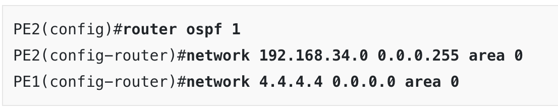
The third line in the config above shows router PE1.. I believe it should be PE2
1 Like
Hello Sam
Yes, this is a typo, thanks for pointing that out! I’ll let @ReneMolenaar know to fix it.
Thanks again!
Laz
Hi Sam, thank you. Just fixed this typo.
Rene
Hi Rene,
I have a problem with my topology in EVE-NG Emulator. In this lesson before starting configuring MPLS, i saw that the GRE Tunnel doesnt work. Below you can verify that the protocol on interface tunnel 0 is down on PE1 side. Can you help me solve this problem?
PE1 Router:
PE1#sh ip inte brief
Interface              IP-Address      OK? Method Status                Protocol
FastEthernet0/0        192.168.23.2    YES NVRAM  up                    up
FastEthernet1/0        192.168.12.2    YES NVRAM  up                    up
FastEthernet2/0        unassigned      YES NVRAM  administratively down down
Loopback0              2.2.2.2         YES NVRAM  up                    up
Tunnel0                192.168.24.2    YES NVRAM  up                    down
PE2 Router:
PE2#sh ip inte brief
Interface              IP-Address      OK? Method Status                Protocol
FastEthernet0/0        192.168.34.4    YES manual up                    up
FastEthernet1/0        192.168.45.4    YES manual up                    up
FastEthernet2/0        unassigned      YES unset  administratively down down
Tunnel0                192.168.24.4    YES manual up                    up
Best regards,
Nádir Almeida.
Hello Nádir
I’m not sure what details you have in your configuration, but if you’re configuring it the same way as in the lesson, it seems that you’re missing a loopback interface on PE2. The loopback is the tunnel source for both ends of the tunnel, and there is no loopback in PE2.
Review the configs again and compare them to the lesson and let us know if you need any additional help.
I hope this has been helpful!
Laz
Hello Laz,
Thank you very much for your help . I verify now that missing a loopback interface on PE2 router. But i created the tunnel GRE with other interface, not loopback. It works.
Best regards,
Nádir
1 Like
Hi,
For the section 1.1 Tunnel between PE routers, I don’t understand why there is a need for the GRE tunnel in the first place. We can just configure iBGP directly between PE1 and PE2.
Hello Son
In this section of the lesson, Rene is showing how it is beneficial to have a GRE tunnel between PE routers. He says in section 1:
Now here’s something to think about…when our goal is to have connectivity between two customer sites, why should all internal P routers know about this? The only routers that need to know how to reach the customer sites are the PE routers of the provider. Why not build a tunnel between the PE routers?
You’re right, there is no need to do this. However, this is one step in the process of proving a point, which is, it is beneficial to have a GRE tunnel between the two PE routers, especially when it comes to a very large ISP network. But the process continues, and shows that this is not scalable, which means, we need some technology that will give us the tunnelling of GRE, but the capability of scaling this to larger networks. And that is where MPLS comes in.
I hope this has been helpful!
Laz
Hi guys,
I’ve heard many times on youtube that MPLS has been replaced by SD-WAN.
What is the relationship between these 2 technologies?
Thanks
Hello Giovanni
Although MPLS and SD-WAN do overlap somewhat, they are two different technologies. Enterprises may choose to implement the edge of their network in different ways and choose to use one technology and architecture over the other, but as technologies, one cannot simply replace the other.
MPLS is primarily (almost exclusively) used to interconnect remote sites of businesses. It is a technology that is implemented within the ISP’s core network and essentially provides VPN services between these remote sites. MPLS as a technology does not actually enter at all into any of the enterprise network equipment configurations. It is a service that is purchased from an ISP, MPLS configurations exist only within the ISP, and as far as the enterprise is concerned, it is a black box.
Conversely, SD-WAN is a set of technologies that allows you to build reliable and high-performance edge network connectivity using multiple lower-cost commercially available Internet access technologies. These are managed intelligently and collectively, and security, speed, reliability, and availability are dynamically provisioned using software. Such an implementation can be used to connect an enterprise to the Internet, as well as interconnect remote sites. However, SD-WAN technology resides wholly within the enterprise’s network and is thus the responsibility of the enterprise itself.
As you can see, these are two completely different approaches to the interconnectivity of remote sites, but each one provides these services in a different way, with a different architecture, and with varying levels of administration by the enterprise itself.
I hope this has been helpful!
Laz
1 Like
This first section mentioned how the P router “pops”/removes a label before sending to the PE router. How does a router know when to remove a label? Is that covered later on in this course?
Thanks,
Buck
Hello Buck
What is being described here is called “Penultimate Hop Popping” or PHP (not to be confused with the scripting language ![]() ). This is performed by P routers that are sending MPLS packets to PE routers. They “know” that the next router is the last hop router, so they perform PHP in order to “save the PE router the trouble of looking at the MPLS label” and providing more efficient communication. More on PHP can be found in the following lessons:
). This is performed by P routers that are sending MPLS packets to PE routers. They “know” that the next router is the last hop router, so they perform PHP in order to “save the PE router the trouble of looking at the MPLS label” and providing more efficient communication. More on PHP can be found in the following lessons:
I hope this has been helpful!
Laz
Hi,
What protocols are supported by MPLS that are not supported by tunneling? Also how MPLS is quicker than tunneling?
Thanks,
Nihar
Hello Nihar
Multi-Protocol Label Switching as its name suggests is capable of encapsulating packets of many network protocols including IP, IPv6, ATM, Frame relay, Ethernet, PPP among others. But remember, GRE as a tunneling mechanism is also able to encapsulate a variety of network layer protocols and even Layer 2 protocols such as Ethernet as well.
So the primary advantage of MPLS is not the fact that it can encapsulate multiple protocols, but that it is capable of scaling much more efficiently than GRE or other tunneling protocols because it uses labels for switching, and because it has mechanisms that allow it to handle multiple customers with multiple sites over the same infrastructure.
MPLS is “quicker” or more efficient than other tunneling protocols because it uses labels. In an environment where you have multiple customers with multiple sites, it would take a very complex routing table and complex lookups to ensure the correct traffic reaches the correct location. Using path labels reduces complexity and increases efficiency. If by quicker you also mean easier to implement then yes, this is true as well, providing easier and simpler scalability.
So the magic of MPLS is scalability for the interconnection of multiple sites of multiple customers over the same infrastructure, something that other tunneling protocols cannot do.
I hope this has been helpful!
Laz
Why ISP use sub-interface in CE Router and also why they use Q-in-Q tagging for MPLS?
Hello Sumit
When designing an MPLS network, the MPLS Layer 3 service consisting of P and PE routers remains the same as a design and a topology, regardless of the access technologies used by the CE routers. Now the access methodology, topology, and the designs used to connect the PE to the CE devices can vary based on many factors including the specific choice of technology, and the needs of the specific enterprise networks.
There are various reasons why subinterfaces would be used on a CE router in an MPLS implementation. ONe such scenario is if you want to have a single CE device connect to two PE devices in a redundant fashion using a gateway redundancy protocol such as VRRP. This is considered a “Hub and Spoke Access with VRRP” scenario. You can find out more about it at this Cisco Documentation including example configurations. This documentation includes multiple scenarios where subinterfaces would be used.
Similarly, if your access network and customer networks require it, you can transmit QinQ information over an MPLS network, which would require you to configure QinQ on your CE devices. You can find out more information about this at this Cisco documentation, which also includes configuration examples.
I hope this has been helpful!
Laz