i have created same scenario in GNS3 and all works fine ,
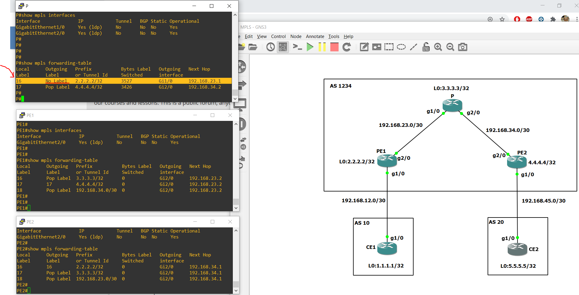
After enabling mpls in PE1, P and PE2 routers i was able to ping CE2 from CE1 and vise verse , but when i compered my output under P#show mpls forwarding-table with your output i found that there is no Pop Label for label 16 in P router i dunno why and what that mean no label?
Hi Rene,
I’m trying to ping 1.1.1.1 from PE2 but I get unreachable, do you know why ?
Hello Charalambos!
This behaviour is to be expected. If you follow along the process of pinging 1.1.1.1 from PE2, you can see the following:
- PE2 has a route to 1.1.1.1 in the BGP table with a next hop of 2.2.2.2, that is, PE1.
- The packet reaches PE2, and PE2 has a route to 1.1.1.1 in the routing table via its link to CE1.
- CE1 receives the ping and must now respond to the sending IP address, which was Gi0/2 with an IP address of 192.168.34.4. But that IP address is not in the routing table or the BGP table, so the router doesn’t know what to do with it and drops it.
This particular communication is not necessary in order to allow MPLS to function. The goal is to have customer devices communicate with each other, and not necessarily specific routers within the MPLS infrastructure.
I hope this has been helpful!
Laz
Hello Ziad
The No Label indicator in your output simply means that there is no label for the destination from the next hop, and Pop Label means that the next hop advertised an implicit NULL label for the destination and the router removed the top label.
In your case, the No Label means that the next hop for the 2.2.2.2/32 prefix, indicated by the 192.168.23.1 IP address, which is PE1, hasn’t assigned a label to this particular destination. I’m not sure why that is happening. I also see some other differences in labels in the PE routers as well. Have you checked that all configurations are the same? Also, do you have connectivity achieved between the CE routers as well as between the PE routers in your topology? In other words, is it functioning correctly?
The labels indicated sometimes change depending on which order the mpls routers have been configured and in what order they become adjacent to each other. If you have connectivity, the differences may simply be due to the order. I hope this information will help you in your troubleshooting. Keep us posted on your progress.
I hope this has been helpful!
Laz
Thanks @lagapidis totally missed that
1 Like
From CE router, all we need to configure our interface connected to PE router in case of default routing which is advertised by Service provider?
Hello Vijay
When configuring the CE router on an MPLS implementation, you must configure it so that it correctly exchanges routes with the PE router. Typically, a CE router will be configured with eBGP between it and the PE router, as you can see in the eBGP Configuration section of the Introduction to MPLS lesson.
But you can also use other routing protocols such as RIP, EIGRP or OSPF when implementing MPLS VPN.
Simply using a default route is not typically correct since MPLS networks usually interconnect remote sites, and not traffic to the Internet. Default routes would most often be used to direct traffic to the internet. There are exceptions, however, like if you choose to backhaul all of your internet traffic over the MPLS network, and have it exit to the internet from another site in your network. But all of that depends upon your particular network architecture.
I hope this has been helpful!
Laz
Hi,
I have a few questions that hope you can point me to the right direction.
If I want to access CE1 1.1.1.1 from CE2 5.5.5.5/32, CE2 will send out an IP packet to PE2, PE2 will look at its FIB (because PE2 receive a IP packet from CE2) and figured out the outbound interface is MPLS enabled interface, so that’s where the “push” label happens, right?
My other question is if I check the FIB entry on PE2 to destination 1.1.1.1/32, it will say something like recursive 2.2.2.2, next hop 192.168.34.3. I understand PE2 just need to know how to send traffic to PE1, then PE1 send the traffic to CE1, that’s why PE2 push a tag that’s assigned to 2.2.2.2(PE1), correct ? So basically PE2 use CEF to figure out L2 rewrite information {next hop(192.168.34.3), outbound interface} and use recursive next hop(2.2.2.2) to determine what label that it needs to add in front of the L3 header to transmit the packet in MPLS core, do I understand this correctly?
Hello Helen
If you send a packet from 5.5.5.5 to 1.1.1.1, then this is what happens step by step:
- The CE5 router, based on the routing table, sends the packet out of Gi0/1 towards PE2
- PE2 receives the packet, and looks at the routing table, and sees the next hop IP for this is 2.2.2.2, or PE1. It will then look in the MPLS forwarding table and see prefix 2.2.2.2 associated with a label and an exit interface. Using this info, PE2 will send out the packet with the appropriate MPLS label out of the appropriate interface. This is indeed where the push or the process of adding an MPLS label takes place.
Yes, your understanding is correct. The word “recursive” is used here because there are two lookups that take place. The first is in the routing table, and the second (recursive) is in the MPLS forwarding table.
I hope this has been helpful!
Laz
Hello,
My company designs customer’s network with either 2 CEs or 1 CE but with 2 link to different PEs. Outbound traffic will most of the time flow through only primary which is configured using BGP weight.
When I look at the configuration, there are also community configuration labeled primary and secondary. I guess it’s for inbound traffic so that it uses primary path.
What should I read to understand more about this configuration?
Hello Mohamad
It makes sense that weight is used to determine the primary path of traffic when you have either two CEs or two links to different PEs. Now the addition of a community within these devices can play various roles, but before you can determine this, it’s a good idea to get a better understanding of what BGP communities are and how they operate. Take a look at the following lesson as well as the subsequent BGP community lessons:
As Rene states in this lesson:
A BGP community is bit of “extra information” that you can add to one of more prefixes which is advertised to BGP neighbors. This extra information can be used for things like traffic engineering or dynamic routing policies.
This is ideal for MPLS scenarios. Take a look at these lessons, and if you have further questions, let us know!
I hope this has been helpful!
Laz
Q-How many option are there to tag the label apart from LDP ??.
Q-Can we configure the EIGRP,RIP,STatic route in mpls core instead of OSPF?.
Q-How P router get to know that i need to perform the PHP ?.
Hello Narad
An MPLS network relies on end to end label switched paths (LSPs) to be established across the network. If LSPs fail, then the MPLS network will fail. LSPs are maintained most often by using the LDP protocol.
However, it is possible to configure an MPLS network to use what is known as MPLS RSVP TE (Traffic Engineering). In such a setup, RSVP is used to set up label switched paths that can be used for TE in MPLS networks. More about this can be found in the following Cisco document:
It is possible to use another routing protocol within the MPLS core, or even to use static routing if you like. The important thing is to ensure that all core MPLS routers are reachable. OSPF is the routing protocol of choice however, especially for larger MPLS networks.
Take a look at this post:
I hope this has been helpful!
Laz
In the section - Why do we need MPLS?
You have suggested to create a GRE tunnel between PE routers?
Why should that be between PE routers? Why cant we have a tunnel between 2 CE routers of customer A, wouldnt that have completed eliminated the BGP from Customer configuration? This would have also created a virtual P2P link over the MPLS cloud. Simple isnt it?
Could you please - what am I missing from understanding?
Hello Darshan
In the first section labeled Why do we need MPLS?, Rene is attempting to create a set of VPNs between customers that are connected to the same ISP without using MPLS. He wants to contrast this solution, which can be cumbersome when scaled up, to the MPLS solution, which is elegant and easily scalable.
One way to attempt to create VPNs between customers is to use GRE tunnels. Now, why is the tunnel being terminated on the PE? The CE belongs to the customer, but the PE belongs to the ISP. Remember that this is a service that the ISP is delivering to the customer, so as an ISP, you would want to have full control over the VPN mechanism, so you terminate the VPN on your own equipment, which is the PE. From the customer’s point of view, there is no specialized tunneling configuration necessary, only the eBGP peering must be established from the CE to the PE. In addition, terminating the GRE tunnel on the PE mirrors more accurately what you end up configuring with the MPLS solution.
Yes, it would eliminate the eBGP peering, but you would have a problem when you try to scale up such a solution. If you have fifty customers with five branch offices each, with overlapping IP addressing, even if you terminate on the CEs, you will find that the whole endeavor of using GRE tunnels will quickly become an administrative nightmare.
I hope this has been helpful!
Laz
Hello Abdulrahman
What you are describing is called penultimate hop popping or PHP. You can find detailed information bout this mechanism at the NetworkLessons note called MPLS Penultimate hop popping.
I hope this has been helpful!
Laz
hi! do you have VPLS course?
Hello Zahid
There is no course on VPLS beyond a brief description in the following lesson:
However, if you are interested in seeing a lesson like this on the site, feel free to visit the Member Ideas page below. There you will be able to make your suggestions and you may find that others have had similar ideas, so you can add your voice to theirs.
I hope this has been helpful!
Laz
Hi Rene , why do we have to source from loopback in order to ping from CE1 to CE2, when mpls is enabled ? by the way i did delete the update-source from bgp
Hello Soufiane
In the lesson, the loopback interfaces represent the internal LAN networks of the remote customer location. The very purpose of MPLS is to interconnect those networks to each other. If the source of the ping was not specified, the router will choose the IP address of the exit interface as the source IP address. Such communication is not a requirement for MPLS.
Indeed, I believe (without having tested it mind you) that such a ping would fail, because CE2 would receive the echo request, but because CE2 does not have a routing table entry for the 192.168.12.0/24 network, the reply would be dropped.
Take a look at the Ping Troubleshooting Concepts note in the NetworkLessons notes for more details about ping and how it chooses the source IP address on a router when it is not specified.
I hope this has been helpful!
Laz