This topic is to discuss the following lesson:
Hello Rene,
I am wondering why the multicast destination MAC address for the announce message in section 5.2.1 is not in the 01:00:5E range?
I thought all multicast frames at layer 2 always had a destination MAC address in the 01:00:5E range, but there its using a destination of 01:1b:19:00:00:00, can you please explain why its using that range if its a multicast frame?
1 Like
Hello Paul
Indeed you are correct that the 01:00:5E range of MAC addresses is the range that is assigned for use with IPv4 multicast addresses. When you have an IPv4 multicast destination address, when encapsulation takes place, a specific mapping mechanism is used to map to this range. You can see this mechanism here:
The Precision Time Protocol (PTP) however, does not use IP at all! It is a Layer 2 protocol. If you take a look at the packet captures in the lesson, you will see that this is the case. For this reason, a specific multicast address had to be defined that would be used for the purposes of PTP. Since no multicast IPv4 or even IPv6 addresses would be used in this process, the ranges reserved for these cannot be used.
That’s why the IEEE reserved two such MAC group addresses for the purpose of the PTP. They define it like so:
Multicast 802 DA as described in IEEE 1588 Annex F
- Two group addresses are specified, for general messages and for peer-delay mechanism messages, but a Profile may use either address for all messages if it wants to.
- 01-1B-19-00-00-00 – a general group address
- An 802.1Q VLAN Bridge would forward the frame unchanged.
- 01-80-C2-00-00-0E – Individual LAN Scope group address
- An 802.1Q VLAN Bridge would drop the frame
You can find out more information about this definition of these MAC addresses at this IEEE definition (slide 5).
In addition, you can find out more about other ranges of multicast MAC addresses at this NetworkLessons note on the topic.
I hope this has been helpful!
Laz
Hello,
I think there is a type in the Event messges, the last one should b Delay_Resp no?
David
Hello David
Yes, you are correct, I’ll let Rene know to make the correction. Thanks for that!
Laz
How can i find that my hardware support PTP or not, to decide the one step/two step sync.
Which hardware i need to look, is it PTP master or slave?
In my case, TM2500C is PTP master and STM32H7 Microcontroller is PTP slave.
Hello Krishnamoorthi
The only way to definitely determine whether your hardware supports PTP (and whether it supports one-step or two-step sync) is to check with the manufacturer’s documentation. If the documentation doesn’t specify it you may need to contact the manufacturer for more details. \
I hope this has been helpful!
Laz
Thanks for this lesson. My question is when you calculated the dalay and offfset.You got 1 as a delay and 10 as an offset. why didn’t you add everything, so that the offset be 11 seconds instead of 10 seconds ?
thanks
chris
Hello Chris
The offset is the difference between the local clock and the master clock. This value remains the same regardless of what the propagation delay is. If the offset were to be calculated at 11 seconds, then at the time of synchronization, the synchronization process would subtract 11 seconds from the clock of the slave. If you go through the process you will realize that this would give us an incorrect result.
So you see, the offset and the delay are two independent values that are unrelated as far as the synchronization goes, so you wouldn’t add them together. To make this clearer, imagine that the delay was 5 seconds. Doing the calculations and the process that Rene goes through in the Clock Synchronization section of the lesson with 5 seconds instead, you’ll see that the result is the same.
I hope this has been helpful!
Laz
1 Like
Hello - Excellent explanation of the PTP functionality.
I have the following questions on the 2-switch example that you presented.
- What will happen if the master switch (SW1) shuts down? Will SW2 become master considering that it no linger receives the announce messages from SW1?
- When the master SW1 comes back it has no idea what time it is (since its not connected to an external accurate time source), will it come up as a slave and update its time from SW2 before it becomes Master again based on its priority?
- If I have a 2-SW topology as you have shown that I want to synchronize in time and no other nodes in the network, Can I configure SW2 in Ordinary Clock mode? In this case would SW2 become a Master given the scenario in items (1) & (2) above?
Thank you
Babar
Hello Babar
Yes, SW2 will become the master clock. The PTP Best Master Clock Algorithm (BMCA) will kick in and the process will result in SW2 becoming the master clock.
When SW1 initially comes back online, it will act as a slave because it has no knowledge of the current time. It will receive the sync messages from SW2 and adjust its clock accordingly. However, once it has updated its time, it will start sending announce messages again. If SW1 is still configured with a higher priority (lower priority number), the BMCA will determine that SW1 should be the master and it will take over that role again. In other words, the process is preemptive.
In order to answer the question, we must clarify a couple of things. There is a difference between the clock type, and the interface role.
The clock type refers to the type of clock the device itself represents. You can have the following types:
- Grandmaster clock (GMC)
- Ordinary clock (OC)
- Boundary clock (BC)
- Transparent clock (TC)
The interface role refers to the role each specific interface on a device has. The two roles are “master” and “slave”. The interface roles should always be chosen in such a way so that the master interface is closer to the GMC. Take a look at this diagram:
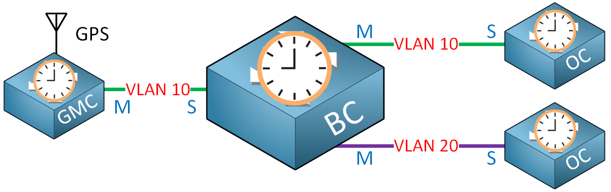
Notice the master role denoted by the “M” is always on the interfaces closest to the GMC, which is the authoritative time source. If the roles were switched, then the source of the time would be an OC, which by definition would be inaccurate. The BMCA takes care of this process.
Now if you had only two switches, there’s no way to explicitly configure one device as an OC. You can however change the priority of one switch so that the SW2 becomes an OC. In the event the master fails, the BMCA will run again, and the OC will become a GMC.
The algorithm determines whether a switch becomes a GMC or an OC, and it also determines the role of the interface. Does that make sense?
I hope this has been helpful!
Laz
Thank you Laz for the detailed answer, It makes perfect sense !
1 Like
I enjoy your website and have learned a lot from the information you provide. I’m disappointed to see you take the time to explain how insensitive the ‘master’ and ‘slave’ descriptions are then say you’ll keep using it. I’ve always abhorred that analogy used in a technical environment. It will only go away when more individuals such as yourself take a stance and remove it from your literature. Waiting for others is not the way constructive change happens. Please do better!
Hello @romoorej
Thanks for sharing this. I looked into all lessons to check this and see if there is anything to update. Here’s what I found:
OSPF (RFC 9454, August 2023)
The IETF published RFC 9454 “Update to OSPF Terminology”, which updates RFC 2328 (and several others). The old “master/slave” terminology has been officially replaced with “Leader/Follower”, and the “MS bit” in the Database Description packet has been renamed to the “Leader (L) bit”. This applies to both OSPFv2 and OSPFv3.
PTP (IEEE 1588g-2022)
The IEEE published the 1588g-2022 amendment, which replaces “master” with “timeTransmitter” and “slave” with “timeReceiver”. The Best Master Clock Algorithm (BMCA) is also renamed to the Best TimeTransmitter Clock Algorithm (BTCA).
I just updated this lesson:
Since the database master/slave terminology doesn’t affect any CLI output or configuration, I changed it to primary/standby.
And this one too:
Puppet’s official terminology is Master/Agent, so I corrected it to that. Chef uses Server/Client as their official terminology, which is already reflected in the lesson.
For the remaining lessons, I will look into updating them, but there’s an important caveat: just because the RFC or standard changes the terminology doesn’t mean Cisco IOS or other operating systems have been updated yet. This was the case for PTP when I published this lesson.
I think with PTP there are some options now where they use the new terminology so I’ll dive into that and see if I can update it.
With OSPF, it shows up here:
I looked into it but as of now, I can’t find any examples of devices that already use the newer terminology.
I’ll keep an eye on this periodically and update it when possible. If a lesson explains “Leader/Follower” but the actual debug output on a router and packet capture still shows “Master” and “Slave”, that would be very confusing for anyone following along. When possible, I want to get rid of the old terminology, but I also want to make sure the terminology in the lessons matches what you actually see on your devices. I’ll do periodic checks and update the lessons once the major platforms have adopted the new terminology in their CLI output.
Rene