Hello Laz,
I want to comment on this suggestion. I encountered the same problem as Ajmal. Indeed some limitations of Packet Tracer. It’s indeed dissapointing when lessons use examples which you can’t replay in Packet Tracer. But to suggest that VIRL (now CML) or GNS is an solid alternative is not the complete truth. Both have their shortcomings as well. CML because there is only an IOS-VL2 switch image available with Gb interfaces (no fa ethernet, which makes it bit more difficult to follow labs where fa interfaces are being used like in this Networklessons course: https://networklessons.com/spanning-tree/spanning-tree-topology-change-notification-tcn.
Rebuilding labs in CML on the basis of examples in networklessons like said above is not always a good thing to do because the results are different.
In CML there is an unmanaged switch as well but you can’t use it for the SPT labs.
GNS3 has its shortcomings as well and as far as I know there is still no good alternative for a managed switch. Only when you use a 3600 series router and turn it into a switch: ttps://www.scribd.com/document/154263104/How-to-Use-Switch-in-Gns3. (Update: It is possible to use a IOSVLs2 switch but this image must be downloaded from the cisco website which is not free (more then 200 euro for a subcription cml).
Actually the best solution is indeed to built your own ccna lab with real hardware but that is not an option for some people with a small purse.
So far I have no experience with connecting a real switch to GNS3 of CML but there is a ton of information on internet howto.
In your answer I miss some nuance and advising GNS3 as an possible alternative for spanning tree labs is something I do not agree with. There are some obstacles.
I appreciate your response to these issues, and I do agree that each possible solution to labbing does have its pros and cons. Packet Tracer is indeed limited in its capabilities for STP and for some other technologies, and you do need to seek other solutions for that.
Although GNS3 and CML do have their drawbacks, they are better than Packet Tracer in several areas. GNS3 can be difficult to deploy sometimes, and CML is not free. But I believe that you can get them to function sufficiently in order to study the content for CCNA and even CCNP level certifications.
As you mention, the only surefire way of making STP and other technologies work flawlessly is to use real equipment. But again, that’s not free.
Ultimately, using these tools (free or not) is an investment in time and money. Obviously, you will try to do it as efficiently as possible, however, some time/money must be spent. Using a combination of these, although not always ideal, should be more than enough to fulfil the requirements of certification.
Thank you for your answer and the link. Of the four I have never used EVE-NG. I think I will give this a try. GNS3 is working now, I downgraded to an older version 2.2 .46 and I managed to add all the IOS images including IOSVL2 and IOSV, ASA firewall and many many other. For the rest I am using Packet Tracer, CML and I invested the last weeks in some real equipment mostly buyed from Ebay.
4 X Cisco Catalyst 2960 24 / 48 T
4 X CIsco Catalyst 3750
1 Cisco WS-C3650- 48 Ports POE switch
1 APC KVM console server 32 ports
1 ASA firepower (firewall) next generation
2 1921 cisco router
3 1841 cisco router
1 Cisco 876-K9 router
1 Cisco IP Phone
Hope that this is sufficient for the CCNA labs and CCNP in the future.
Your whole lab setup, with your real equipment as well as your GNS3, Packet Tracer, CML, and now your experimentation with EVE-NG are more than enough to cover all of the topics you need to become proficient for CCNA and CCNP level certifications. Many people have been successful in their certifications with much less than what you have, so you are in a very good position. Labbing is one of the most important parts of learning for certifications, so I belive you’re covered for virtually all topics.
There is a topic that I am very confused about and that’s the Max Age timer decrementation.
Each time a switch receives a BPDU from the root bridge, it will decrement the Max Age timer by 1?
So if there are two switches connected to the root, the timer will be as following?
root - 20
SW1 - 19
SW2 - 18
If so, why exactly does this happen? Doesn’t this timer specify how long do you wait after ceasing to receive BPDUs from your neighbor? So why the decrementation?
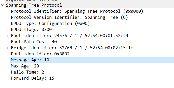
Hmm… that doesn’t seem to be the way the Max Age timer works. I think you’re probably referring to the Message Age, which is a field found within the BPDU header. This value actually starts out at 0 when the BPDU is sent by the root bridge, and it is incremented by 1 every time it is received and relayed by another switch.
When a switch receives a BPDU, it checks the BPDU’s Message Age and compares it with its own Max Age timer. If the BPDU is considered fresh (i.e., the Message Age is less than the Max Age), the switch processes the BPDU and resets its own Max Age timer for that port. If the BPDU Message Age exceeds the Max Age, the BPDU is discarded, and the switch might start considering changes in topology since it hasn’t received a valid BPDU for a while.
The Message Age value actually works more like TTL does for IP. It prevents BPDUs from looping throughout the topology.
Now this begs the question, if you have an STP topology that has some switches more than 20 “links” away, then the Message Age will always be larger than the Max Age for any switches that are that far from the root bridge.
Well it is best practice to keep your Layer 2 topologies much smaller, and you should never encounter such a large L2 STP topology. However, if you do, you would have to adjust the Max Age timer appropriately in order to allow for such large L2 infrastructure.
Why were these numbers chosen? Because they work. Even though the message age is not really in seconds, but it measures hops, it is compared to the Max Age which is in seconds. It may sound strange, but the design has been tested, and these values and these mechanisms work, for topologies that are of reasonable sizes. Does that make sense?
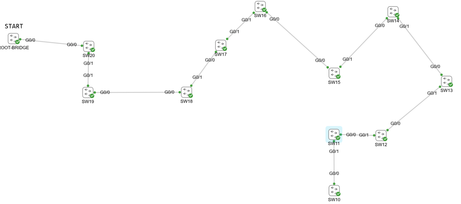
I’ve purposely connected the switches this way to demonstrate something. On SW20 (the switch directly connected to the root bridge), it takes it 20 seconds to respond if I cut the root bridge down.
I therefore don’t think that this timer is reset each time a BPDU is received. What actually happens is the Message Age of the BPDU is subtracted from the Max Age timer. Since the message age looks like this before it hits SW10
SW10 will therefore subtract 10 from the max age. It will therefore cause it to respond 10 seconds faster than it should. So the further away you are from the root, the faster the BPDU ages out.
So apart from preventing potential looping BPDUs, it also causes switches that are further away to age out this BPDU faster. I suppose that the reason for this is to account for the time it takes to propagate the BPDU all the way there and to not have the downstream switches delayed since it would be bad if the bottom of your topology had to wait 20 complete seconds although, for example, 5 seconds have already passed since this BPDU was created.
Great experiment! It truly sheds light on the inner workings of these STP timers/aging mechanisms. Indeed, the documentation you shared states it very well:
The age timer starts at the message age that is received in that configuration BPDU.
So if the age timer begins at message age, which is a value of 10, then it will reach the max age of 20 in 10 seconds, which is what you saw in your topology. Your experiment gives greater understanding of this statement, thanks for sharing!
Hello , if thats the case then there would be a chance of loop and reconvergence will happen to block the port, right ?. quite tough to comprehend this statement.
There is no such thing as a dumb question. Your question is a good one because when answered, it will help in your understanding.
Yes, by definition, a root port is the port which is “closest” to the root bridge. This is measured by the cost of the path to the root bridge. To find out more about how the cost is determined, take a look at this lesson:
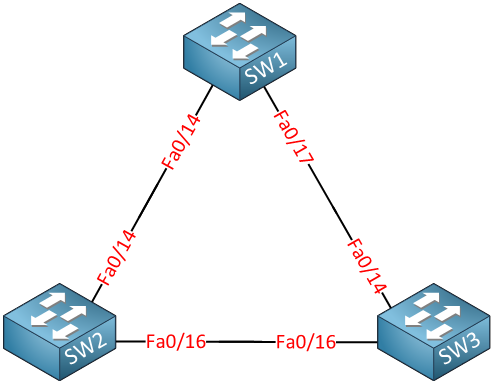
Now just to clarify, this is the topology that we are using.
In the post, Rene refers to SW A, B, and C, but those correspond to SW1, 2 and 3. According to the original post that Rene was answering, we assume the link between SW1 and SW3 has gone down.
The root switch is SW1. So Fa0/14 becomes the root port on SW2 because it is the “closest” port on that switch to the root. On SW3 the Fa0/16 becomes the root port for obvious reasons. That means that the Fa0/16 port on SW2 must become a designated port. It can’t become a root port, because SW2 already has a root port. It can’t become a blocked port, because we have a root port on the other end, and root ports NEVER connect to blocked ports. So, Fa0/16 on SW2 must become a designated port. Does that make sense?
I did this test in the same triangle topology; all the ports of the non-root bridges are in designated and root port. No port went to Alt state. if we enable BPDUfilter then there would be a loop in the environment , right ?.
That response from eight years ago was incorrect, thank you for catching that! I have since edited the post to reference a NetworkLessons note on the topic.
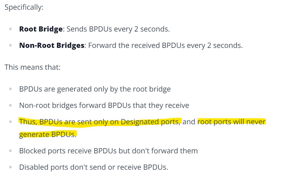
The highlighted statement confused my understanding of the of the concept 1.Even Non-route bridges also have the designated ports . will that generate BPDUs?
all the root bridge ports are in designated role, so all of them will generate the BPDU and sent out to connected non-route bridge ports which can be in any port role , right ?
could you shed some light on this ?.
When it comes to STP, what should be taken into consideration when I am deciding which one of my switches should be the root bridge? Like how would I decide?
Ah I see, you tried the experiment that @ReneMolenaar suggested in his post and you got it to work. Yes, you can use BPDU Filter to achieve this, and if you do, you are right there would be a loop in the topology.
For more information about the BPDU Filter feature, take a look at this lesson:
I can understand the confusion. I have since updated the text to be clearer. I will explain further here:
The text refers only to classic IEEE 802.1D STP. In this type of STP,
Only the root bridge generates Control BPDUs.
Since all ports of a root bridge are designated ports, only designated ports will generate control BPDUs. (Root bridges don’t have root ports or blocked ports).
Since the root bridge generates control BPDUs, non-root bridges will receive control BPDUs on their root ports. These are the ports facing the root bridge.
Since control BPDUs are always forwarded downstream, they will never be forwarded out of a root port (which would be in an upstream direction).
So the phrase “root ports will never generate BPDUs” simply comes from the fact that root ports point “upstream” and control BPDUs are never sent upstream, but always downstream.
Keep in mind that the above is only about Control BPDUs. TCN BPDUs are generated by any STP bridge, and these are sent upstream, and for TCNs, they are sent out of the root port.
It is true that all root bridge ports have the designated role and they will generate BPDUs. But by definition, all of the ports of non-root switches connected to the root bridge will be in the root port role by definition. Because they connect to the root bridge. So all BPDUs sent by the designated ports of a root bridge will be received by root ports.
This is an excellent question. When deciding which switch should be the root bridge in your STP topology, there are several factors you should consider:
Location: Ideally, the root bridge should be located at or near the “center” of your network. Practically speaking, this means that it should be located in such a way as to ensure the shortest path to all other switches. This will help to reduce the time it takes for STP control frames to travel across the network, reducing STP convergence times.
Processing Power and Memory: The root bridge will process more data than other switches, so it should have sufficient processing power and memory to handle this load without slowing down.
Reliability: The root bridge is a critical component of your network, so it should be a switch that is known to be reliable and unlikely to fail.
Network Design: The choice of the root bridge also depends on the design of your network. If you have multiple VLANs, you might need to consider multiple root bridges at various locations, depending upon where each VLAN is configured.
These are the main considerations that you should take into account in most cases.
In my post, I mentioned that much like the MAC address is used as a tie breaker for STP, IPv4 addresses are also used as tie breakers in Layer 3 protocols. IPv4 addresses are not used as tie breakers for STP, and you’re right that would be strange if that were the case.