Introduction to the OSI Model

Hi Sreejith,

I would say SONET/SDH belongs to layer 1. It specifies the physical layer and you can run different L2 protocols (including Ethernet) on top of it. It’s not like frame-relay which has a clear specification of L1 + L2.

The main difference is that the physical layer is different between SONET on one end and Ethernet on a LAN on the other side. When you receive something from the SONET side, it goes from the physical layer to the data link layer and you end up with an Ethernet frame. The outgoing interface is selected, the frame goes from the data link layer to the physical layer and is then transmitted.

Rene

I have the same doubt. I´ve read L2 (eth frames) doesn’t perform error CORRECTION but error DETECTION.

Error Correction (Retransmission) is only on L4 TCP.

Is that correct ?

1 Like

Hi Rene,
Thanks for your reply . I thought STS frames are the layer-2 protocol for Sonet/SDH interface(layer-1) like Ethernet frame for Ethernet interface (layer-1). Once a packet reaches from an Ethernet interface on a router and if it’s destination points to Sonet interface on the same router , how the router will forward it ? I believed the router will de-encapsulate the Ethernet frame , take the IP packet , do some routing \ARP table look ups, encapsulate the IP packet in STS frame and forward towards the Sonet interface (OC signal : Optical link). Please correct me if I am wrong :slight_smile:
Thanks,
Sreejith

Hi Juan,

That’s right. Ethernet frames have a FCS (Frame Check Sequence) so a device can validate if the frame is OK or not, but there is no error correction.

TCP does have error correction, it uses retransmissions.

Rene

1 Like

Hi Sreejith,

It’s not really layer 2 but it’s more like layer 1.5…it doesn’t really fit in perfect with the OSI model but after all, the OSI model is just a reference model.

You are right about how the router does encapsulation / de-encapsulation. On one interface, the router receives some Ethernet frame. It de-encapsulates it and ends up with an IP packet. It checks the destination of the outgoing IP packet in the routing table and finds out that the outgoing interface is the Sonet interface.

It then encapsulates the IP packet in a new Ethernet frame, encapsulates it in an STS frame and forwards it out of the Sonet interface.

Rene

When I learned the OSI Model years ago. I’ve always like this saying.

Please, Don’t, Never, Throw, Sausage, Pizza, Away

1 Like

Hello Rene,

I just wanted to clarify the application, presentation, and session layer. Basically when you go onto your browser (Firefox which is the application) and put www.google.com your computer sends a request to the webserver to request the webpage by using HTTP protocol. The presentation layer makes sure the data at the application layer is in a readable format. The session layer takes care of the sessions meaning your not the only one making a request to www.google.com. Could you please confirm if I’m correct!

Cheers!

Hello Rene,

Can you please explain the following.

  1. How is data is formatted in the correct way
  2. How error detection is done
  3. How does it make sure data is delivered reliably

Cheers!

Hello Iynkaran

First of all, the application layer is not where the actual applications on your computer function. These software applications sit on top of the OSI model and are not actually part of it. The application layer is the layer where protocols such as HTTP/HTTPS, FTP, SMTP, IMAP and others function. These protocols are then leveraged by software applications. This is what makes software applications “network aware” if you will.

From a practical standpoint, the model that is primarily used in today’s networks is the TCP/IP model. This model incorporates parts of the session and presentation layers into the transport and application layers resulting in a model with fewer layers.

So in your example of a web page, the web browser would use the HTTP protocol (Application layer) to communicate between the client (web browser) and the server (Web server). HTTP contains within its mechanisms the functionality of the presentation layer, so we don’t actually see the presentation layer in the Wireshark packet capture. The presentation functionalities essentially allow the information that is received from lower layers to be presented in a manner that the HTTP protocol, and the client can understand and display.

Similarly, the session layer functionalities are incorporated into the transport layer. The sessions that are being referred to here are those between the host and server, that is between the web browser and the web server and do not involve the sessions of any other hosts.

For more information about the TCP/IP model as compared to the OSI model, take a look at this lesson:

I hope this has been helpful!

Laz

2 Likes

Hi, Rene.

I am a new student in networking and I am a bit confused about not being able to skip any layer of the OSI model because I heard from another source that you can indeed skip certain layers of the osi model and not every layer will be filled during data transmission. I am confused because you both seem to be well respected experts in technology and both have ccie’s. I am not sure if it is allowed to say the person but they put the osi model as reference model and not a reverence model.

Hello Bion

The OSI model is used as a teaching tool to show how network communications take place, and to identify the role of various parts of the network. These mechanisms are associated with specific layers in the OSI model. When you have data such as the contents of an Email, this data must be broken down, encapsulated at each layer with headers that tell the networking devices how to handle the specific piece of data. You can’t skip a layer simply because a TCP header is necessary to allow for communication between the email client and server, the IP header is necessary to be able to route the packet from host to router to router to router to destination address, and the Data link layer is necessary to be able to move the information on a hop by hop basis. The physical layer is also necessary to be able to interpret the signals that exist on the medium (fiber, copper, wireless).

If you skip one of those layers, the whole thing will not work. However, having said that, it really depends on what you mean when you say you “skip” a layer. You may say this about the session or presentation layers simply because those are incorporated into the Application layer when it comes to TCP/IP. Or you may say that you “skip” the Ethernet functionality if you use other technologies such as PPP at that layer, but that’s not technically skipping the Datalink layer. So when someone tells you you can “skip” a layer, it should be explained as to what that actually means. As far as TCP/IP communication goes, no such skipping (beyond what I explained above) can occur.

I hope this has been helpful!

Laz

1 Like

Yes. Thank you, Lagapides. It does make it more clear and believe he was speaking about the upper layers from session and up. Depending on application is being used.

1 Like

Hello @lagapidis,

what would you say are the negotiations/agreements that happen at each layer? For example at Layer 1 physical - we have speed and duplex negotiation.

Regards.

Hello sales2161

There are a whole series of characteristics and parameters that must be standardized and agreed upon by manufacturers and standards organizations at each layer of the OSI model. I’ve listed some parameters for some layers below, but these lists are by no means exhaustive.

On the physical layer, the parameters that are defined include the type of medium used and its characteristics. Copper, fiber, or wireless, including some minimum standard parameters of the medium defined by specific standards such as IEEE802.3 or 802.11 for example. These define things like type of copper used, type of glass used for fiber, minimum distance of physical cable, method of encoding (placement of bits on medium) and signalling (nature of the phenomenon traversing the medium such as voltage/light/EM waves). Physical layer also includes connector types, voltages, wavelengths, and signal strengths on the media. Most of these standards are not actually configurable on the devices, but are predetermined by the manufacturers for particular interfaces and components. Speed and duplex settings as you describe them are primarily an Ethernet issue and are found at the Datalink layer.

On the datalink layer, many more things can be configured, although some are built in. Configurable parameters include speed and duplex, and interface MTU, while interface types such as Ethernet, serial, and Wi-Fi are built in and cannot be modified. Physical addressing, logical link control operation and multiaccess mechanisms such as CSMA/CD and CSMA/CA and service protocols like STP, VTP, CDP, and DTP are all found within the datalink layer.

The network layer is where IP lives, and the parameters here are endless. IPv4, IPv6, routing protocols, routing mechanisms, GRE tunneling, VPNs, IPSec, and many others are agreements and standards that exist on this layer.

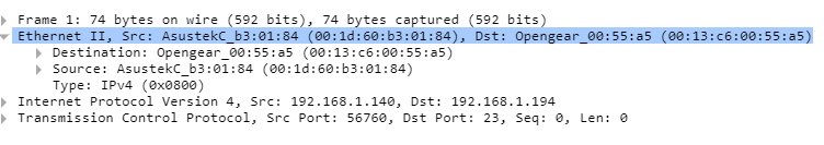
The transport layer similarly has many parameters including the protocol being used such as TCP, UDP, as well as other specialized protocols like RTP and RTCP. Addressing on this layer involves ports, and TCP in particular has reliability and error checking mechanisms that are agreements that take place at this level.

As we go higher, the number of parameters increase steadily, and when we reach the application layer, the detail becomes almost endless. Each application layer protocol has within it an enormous number of parameters that require negotiation in order for endpoints to function correctly.

Although by no means exhaustive, I hope this gives you an idea of the many agreements and parameters that must be in accord for communication to occur…

I hope this has been helpful!

Laz

1 Like

That’s a nice explanation - does this mean from Session to Application the negotiation/agreement will depend on the application protocol being used?

Hello sales2161

I would have to say yes. Although we use the OSI model for training purposes, in actual practice, we use the TCP/IP model. In this model, the session and presentation layers are incorporated into the application layer. So yes, for those two layers of the OSI model, in practice, negotiation takes place within the application layer, thus within the confines of the application protocol being used.

I hope this has been helpful!

Laz

Hello

I’m doing ccna course and I’m doing the wire shark just beginer in osi model chapter .

First packet we try to read from down is ether frame . it’s 908 bytes and second line Ethernet 2 line on wireshark is showing it had captured source and destination Mac address

So any help I can get to understand it ?
Thanks

Thanks

Hello Moeed

When looking at a wireshark capture, in the bottom left pane you will see various lines. In general terms, each line refers to a different layer of the OSI model. For example, take a look at the following:

The first line that says “Frame 1: 74 bytes on wire (592 bits)” can be considered the physical layer, and it shows the total number of bytes that are actually placed on the wire, or on the transmission medium. This includes the Ethernet header and the encapsulated payload, which includes the IP header and payload, which in turn includes the Transport layer header and payload.

The second line shows the information found in the Ethernet header, which includes both source and destination MAC address. You can find out more about the Ethernet header and its contents at the following lesson:

I hope this has been helpful!

Laz

hello
if I want to send one photo using my WhatsApp to my friend WhatsApp. How the data will go in layer 1? if am connecting throw wi-fi wireless .
7-Application
6-Presentation
5-session
4-transport
3-network
2- Data link
1-Physical

Hello Faisal

Layer 1 in this case would use the wireless medium. When the data link prepares the frames containing the information of your photo and hands the frame down to the physical layer, the bits of that frame are encoded onto radio waves. Encoding is the process by which bits (ones and zeros) are translated into waveforms that can be interpreted by wireless transceivers. There are many methods of encoding.

Some of the simplest that you can research include Amplitude Shift Keying (ASK), Frequency Shift Keying (FSK), and Phase Shift Keying (PSK). These simply define how a radio wave is to be modulated, or modified by the series of bits delivered by the layer above, so that the information is contained within the radio wave, and can be interpreted on the other end. Wi-Fi however uses more complex encoding schemes, but the idea is the same.

I hope this has been helpful!

Laz