This topic is to discuss the following lesson:
Hi Rene,
Great ![]()
What about the FCS when changed MAC on every L3 segment ? Its recalculate or not ? ? Header Checksum indicates value of IP header only , no upper layer (TCP/UDP Header+Data) where as FCS indicates total value including Ethernet Heaer + IP Header+ TCP/UDP Hearder+ Data , right ? Please correct me if i am wrong .Many Thanks
br//
zaman
Hello Mohammad.
You are correct, the FCS is calculated on every hop of the journey of a datagram. It is recalculated because the header of the frame in each hop changes. The header checksum of the IP header remains the same for the whole journey since the IP packet does not change.
I hope this has been helpful!
Laz
1 Like
Hi Laz,
@lagapidis
But as Rene said, Header checksum will get recalculated at every hop since TTL gets decremented. Please correct me if I am wrong?
1 Like
Hello Rahul
Yes, you are correct, the header checksum is recalculated at every step, I stand corrected.
Thanks for catching that!
Laz
Hi. Rene,
Thx for your nice Tutorial.
I have one question. Is Routing table execute sequentially (Top to bottom) & take action immediately like ACL do with his per ACE?? Appreciate your quick response in this regards .Thx
br/
zaman
Hello Mohammad
A routing table is not executed in the same way as an ACL. When there is a destination address, it is compared to each entry in the routing table and is matched with the most accurate entry. For example:
Let’s say the destination IP is 10.96.4.7 and the routing table includes the following destinations:
172.16.1.0/24
10.96.0.0/16
192.168.7.0/24
10.96.4.0/25
The router will look at each destination. Here there would be two matches: 10.96.0.0/16 and 10.96.4.0/25. Once the router finds the first match, unlike an ACL, it will continue searching through the routing table to find a more accurate match. In this case 10.96.4.0/25 is more accurate, so this one is chosen.
Keep in mind that a routing table usually has the destinations in some sort of numerical order, so it does save time in finding the most accurate route.
I hope this has been helpful!
Laz
Hi Laz,
Many Thanks for your reply as always ![]()
So , if you have 6+lac (BGP Prefix + Infrastructure prefix ) prefix in a routing table then Router will check with all 6+lac prefix from top to down and find out more specific entry and send the packet to exit interface , right ??
I cant understand that you have wrote “Keep in mind that a routing table usually has the destinations in some sort of numerical order, so it does save time in finding the most accurate route”. could you please clear to me .Thx
br//zaman
Hello Mohammad
For example, take a look at this routing table:
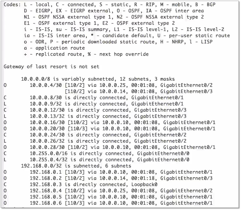
You will see that the IP addresses are listed in numerical order: first 10.X.X.X then 192.X.X.X etc. This means that if your destination is 10.0.0.17 and you have looked through all the 10.X.X.X addresses, you don’t actually need to try to match with the rest of the entries since you know there are no more 10.X.X.X addresses in the table. This makes searching somewhat more efficient.
I hope this has been helpful!
Laz
1 Like
Hi Rene,
same scenario how arp will resolution work in case in static route 192.168.2.0 (S 192.168.2.0/24 [1/0] via 192.168.12.2) instead of nexthop as 192.168.12.2 i will configure interface Gi0/2 on R1:
ip route 192.168.2.0 255.255.255.0 Gi0/2
how difference it will make and where actually it is useful . Thanks in advance .
Hello Sameer
If you have the following static route in R1:
ip route 192.168.2.0 255.255.255.0 gigabitethernet0/1
then the following will take place:
- The packet with a destination of 192.168.2.2 will reach R1, and the routing table lookup will match this static route.
- Because this exit interface is Ethernet which is a multi access technology, there may be many hosts (potential next hop routers) connected to it. Because it doesn’t know the next hop IP, R1 will send out an ARP request for the destination IP of the packet. (If this was a serial link, which is a point to point technology, the packet would be sent out the interface directly).
- The ARP request would reach R2. If proxy ARP is enabled on R2, it will then send out ARP requests which will reach H2 and it will get a response. If proxy ARP is not enabled, the ARP request will not be responded to, and the routing will fail. Proxy ARP is enabled by default on Cisco routers.
- R2 will then respond to R1’s ARP request with its own MAC address, allowing the packet to be routed.
I’ve seen this setup used in some large private networks. The one I have in mind is specifically a private government network. Each entity, such as a municipality, is provided with an IP address range such as 10.96.0.0/21 for example. The edge router for the entity advertises this address range to the private network, but it has no knowledge about how this range is further subnetted and routed within the municipality itself. Any packets destined for the internal network of the municipality will match a static route with an an exit interface (the interface facing the internal municipality network), and the edge router will send an ARP request towards the internal network to ask for a MAC address. The internal router will then use proxy ARP, and will send its own MAC address as the next hop MAC.
Such a setup allows the operators of the main network to route traffic to an internal entity, such as a municipality network in this case, without having to know the internal routing nor having to participate in any internally configured dynamic routing protocol.
I hope this has been helpful!
Laz
1 Like
Hi,
I understand why ARP is important in regard to layer 2 but why is ARP important when it comes to IP routing? why should a router first know another router’s ARP before sending the packet? isn’t knowing the IP address just enough?
i appreciate your response.
Hello Walter
When one host communicates with another over a network, the IP addresses are used to establish end to end communication. This means that the source and destination IP addresses in the IP header remains the same during the whole journey of the packet (This is not the case with NAT, but that’s a different story).
The source and destination destination MAC addresss in the Ethernet frame however (Layer 2), changes for each hop of the journey. Every time a router is encountered, the packet is de-encapsulated, and the frame header is replaced with a new header, with new source and destination MAC addresses.
Imagine a packet arrives at a router somewhere in the network. The router de-encapsulates the packet to Layer 3. It will read the destination IP address, and using the routing table, will decide out of which interface to send it, as well as the next hop IP.
Next the router must re-encapsulate the packet. This means it needs to place a source and destination MAC address in the header of the frame. The source MAC address is that of the exit interface it has chosen. The destination MAC address must be that of the next hop router.
At this point the router knows the IP address of the next hop router from the routing table. But does it know the MAC address of the next hop router? This is where ARP comes in. If it doesn’t know it, it will send out an ARP request for the MAC that corresponds to the next hop IP. It will populate its ARP table to use that MAC in the future as well.
So ARP is used to determine the MAC address of the next hop router, something that is necessary in order to successfully create the Ethernet header and send the packet/frame out of the exit interface.
I hope this has been helpful!
Laz
1 Like
clear and sound. thank you for taking time to respond with deep and precise explanation.
1 Like
Hi Laz ,
Thanks , I agree with the explanation you have provided . I asked this question as i was looking for “Directed Arp” feature (rfc 1433) . I am not aware of this term , may be this scenario is related to this . Can you please share if you have information about this .
Hello Sameer
Directed ARP is used in a different situation than that described in your previous post. It is used in a scenario that is not often encountered nowadays. It requires a topology similar to the following:
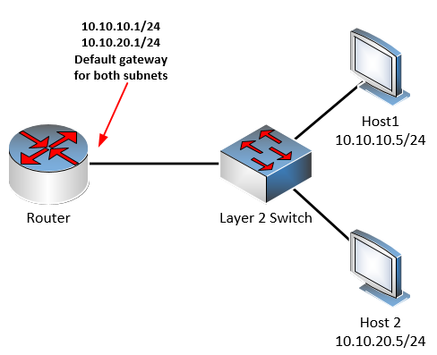
Notice here that there are two subnets (10.10.10.0/24 and 10.10.20.0/24) on the same network segment. Notice also that the router interface, which functions as the default gateway for these two networks, has two IP addresses, one in each subnet. Even though Host 1 and Host 2 are on the same Layer 2 segment, they have IP addresses in different subnets so in order for them to communicate, they must do so via the router.
Note that the router interface is not configured with subinterfaces, but the physical interface itself is assigned multiple IP addresses.
Now such a scenario, strange as it may seem, will work just fine, assuming you can assign two IP addresses in two different subnets to the same router interface, something that Cisco routers do not support.
Now directed ARP becomes useful in this case because it would allow Host 1 and Host 2 to communicate directly, and not via the router, even through they are on different subnets. This is possible because they are on the same physical link. Directed ARP uses normal ARP packets with the same format. The “intelligence” for directed ARP is found in the router which has the two IP addresses on the same subnet.
When the router receives an ARP packet from Host 1 for the destination IP of Host 2, the router “knows” that these two hosts, are on the same physical segment, because both subnets are found on the same physical interface of the router. So the router will respond sending the MAC address of Host 2 as the destination MAC. So when Host 1 encapsulates its packets, they’ll look like this:
IP Header
- Source IP address 10.10.10.5
- Destination IP address 10.10.20.5
Ethernet frame header
- Source MAC: Host1MAC
- Destination MAC: Host2MAC
The result is a direct communication between the two hosts.
Now where would you actually use this? According to the RFC it says:
Multiple IP networks may be administered on the same link level network (e.g., on a large public data network).
Today, it is not considered good network design to interconnect many hosts with different subnets on the same network segment “in a large public data network”. This would create one large broadcast domain resulting in performance degradation, as well as potential security risks. However, back in 1993 when the RFC was written, it was a more acceptable practice, as the volume of traffic on networks as well as the number of potential hosts was much smaller, and such an implementation would indeed be much simpler, requiring only a single router for multiple subnets sharing the same network segment.
So you won’t encounter directed ARP often in today’s networks, but it’s quite interesting to find out more about it.
I hope this has been helpful!
Laz
3 Likes
Hi Rene/Laz,
First of all thanks for this explanation which i have been searching for a long time.You explained it very well ,But i have few doubts ![]()
-
Some times we say host send IP packet and some time say host send Ethernet frames,
how is this possible ? I have been too confused please clear this out? -
We knows router is a layer 3 device and it forward packet but here we can see router receiving Ethernet frames (a/c to Dencapsulation which can be possible ) so how router can send Ethernet frame encapsulating ip packet to the next router ?
3)As per my knowledge PC is a transport layer device which is responsible for host to host delivery then how it can send packet or frame?
Could you explain it like per layer encapsulation or de-encapsulation process for any connected device(PC to Router or Router to Router )
Hello Pradyumna
Different devices function at different layers of the OSI model. Here is the model just for reference.
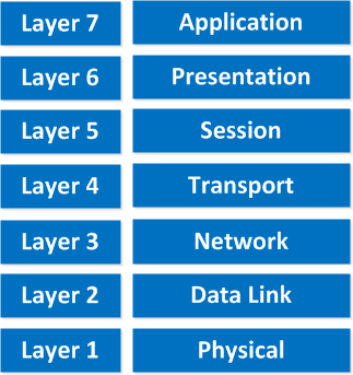
Now when we say that a particular device functions at a specific layer, it means that that layer and all layers below it are involved. For example, a router is a Layer 3 device, so it has functions and operations at Layers 1 to 3. It functions in the physical, data link, and network layers. A PC, which can be considered an Application Layer device, functions at Layers 1 to 7, so all layers are involved.
For this reason, a router will take packets, which function at Layer 3, encapsulate them into frames, which function at Layer 2, and place them on the medium (wire, fiber, wireless) which involves Layer 1. Similarly, a PC, will take application data (HTTS for example), segment it into segments or datagrams at Layer 4, encapsulate those into IP packets at Layer 3, encapsulate those into Ethernet frames at Layer 2, and encode those onto the wire or wireless, representing bits as voltages, or EM waves.
To emphasize the point, take a look at the following image:
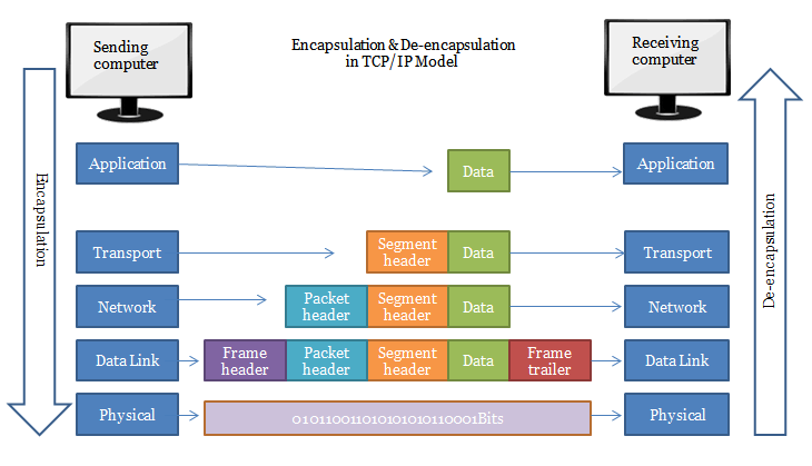
Notice that inside the FRAME we have the IP PACKET. And inside the IP PACKET we have a SEGMENT. These are entities that exist, even when we talk about other layers. The Packet is there, even if we are saying we are sending a frame for example.
In the lesson, when it is stated that “the router sent a frame”, it means we are focusing on the Layer 2 operation of the router at that point. That frame contains the packet, which contains the segment, and so on, but the emphasis is on the functionality of Layer 2 for that particular instance.
Just one more diagram to clarify. Here we have the encapsulation process described at the source, and the decapsulation process described at the destination.

But notice, that any routers along the way, which are layer 3 devices, will take the data, decapsulate it up to layer 3 (in order to read the IP addressing information for routing) and then encapsulate it with new layer 2 header information, and send it along its way. Notice that the decapsulation took place only up to Layer 3, and routers are Layer 3 devices.
I hope this has been helpful!
Laz
5 Likes
Thank you so much Laz for this wonderful and unexpected way of explanation.
And second thank you for always responding to my query.
One more query is that, Is ip routing process called Packet flow ?
Hello Pradyumna
IP routing is the process that a device goes through to decide out of which interface a received packet should be sent, based on the destination IP address.
Packet flow, also called traffic flow, refers to a series of packets that are being sent from one host to another. All packets within the flow are identified by their source and destination IP addresses. All packets with the same source and destination address, that are sent within a particular time frame, are considered part of the same flow. Sometimes, the transport layer port numbers are also included to further define flows, based on the ports, and thus the applications, that are being used.
I hope this has been helpful!
Laz
1 Like