Hi all,
I’m studying IPSec standard and I’ve got the following lab in Cisco Packet Tracer.
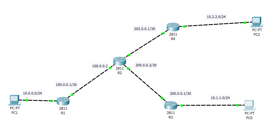
I want to configure two IPSec tunnels, one between R1 and R3 and the second between R1 and R4. Also I want traffic between R4 and R3 to go through R1. I can ping PC0 from PC1 and I can ping PC2 from PC1, but for some reason I can’t ping PC0 from PC2. I’ve checked configuration several times and it looks correct. Can anybody help me, what might be wrong? Here is the configuration of all three routers. Thanks!
hostname R1
!
 crypto isakmp policy 1
 encr aes
 authentication pre-share
!
crypto isakmp key cisco address 200.0.0.1
crypto isakmp key cisconew address 202.0.0.1
!
crypto ipsec transform-set AES128-SHA esp-aes esp-sha-hmac
!
crypto map MAP1 10 ipsec-isakmp
 set peer 200.0.0.1
 set transform-set AES128-SHA
 match address 101
!
crypto map MAP1 20 ipsec-isakmp
 set peer 202.0.0.1
 set transform-set AES128-SHA
 match address 102
!
!
interface FastEthernet0/0
 ip address 100.0.0.1 255.255.255.252
 duplex auto
 speed auto
 crypto map MAP1
!
interface FastEthernet0/1
 ip address 10.0.0.1 255.255.255.0
 duplex auto
 speed auto
!
ip route 0.0.0.0 0.0.0.0 100.0.0.2
!
!
access-list 101 permit ip 10.0.0.0 0.0.0.255 10.1.1.0 0.0.0.255
access-list 101 permit ip 10.2.2.0 0.0.0.255 10.1.1.0 0.0.0.255
access-list 102 permit ip 10.0.0.0 0.0.0.255 10.2.2.0 0.0.0.255
access-list 102 permit ip 10.1.1.0 0.0.0.255 10.2.2.0 0.0.0.255
hostname R2
!
interface FastEthernet0/0
ip address 100.0.0.2 255.255.255.252
duplex auto
speed auto
!
interface FastEthernet0/1
ip address 200.0.0.2 255.255.255.252
duplex auto
speed auto
!
interface FastEthernet1/0
ip address 202.0.0.2 255.255.255.252
duplex auto
speed autohostname R3
!
crypto isakmp policy 1
encr aes
authentication pre-share
!
crypto isakmp key cisco address 100.0.0.1
!
crypto ipsec transform-set AES128-SHA esp-aes esp-sha-hmac
!
crypto map MAP1 10 ipsec-isakmp
set peer 100.0.0.1
set transform-set AES128-SHA
match address 101
!
interface FastEthernet0/0
ip address 200.0.0.1 255.255.255.252
duplex auto
speed auto
crypto map MAP1
!
interface FastEthernet0/1
ip address 10.1.1.1 255.255.255.0
duplex auto
speed auto
!
ip route 0.0.0.0 0.0.0.0 200.0.0.2
!
access-list 101 permit ip 10.1.1.0 0.0.0.255 10.0.0.0 0.0.0.255
access-list 101 permit ip 10.1.1.0 0.0.0.255 10.2.2.0 0.0.0.255hostname R4
!
crypto isakmp policy 1
encr aes
authentication pre-share
!
crypto isakmp key cisconew address 100.0.0.1
!
crypto ipsec transform-set AES128-SHA esp-aes esp-sha-hmac
!
crypto map MAP1 10 ipsec-isakmp
set peer 100.0.0.1
set transform-set AES128-SHA
match address 101
!
interface FastEthernet0/0
ip address 202.0.0.1 255.255.255.252
duplex auto
speed auto
crypto map MAP1
!
interface FastEthernet0/1
ip address 10.2.2.1 255.255.255.0
duplex auto
speed auto
!
ip route 0.0.0.0 0.0.0.0 202.0.0.2
!
access-list 101 permit ip 10.2.2.0 0.0.0.255 10.0.0.0 0.0.0.255
access-list 101 permit ip 10.2.2.0 0.0.0.255 10.1.1.0 0.0.0.255