I was wondering if I could advertise labels without LDP. I found this for anyone who is interested.
I need to lab this.
Hello Justin
Could you run MPLS without LDP? Well the short answer is yes you can. You can use MP-BGP to share those labels. Now should you? Well that’s a different story. It’s not as scalable, and it requires that you ensure you separate customers using VRFs and you may need to make your P routers route reflectors. In any case, take a look at this Cisco community thread as well that sheds some more light on this.
If you do end up labbing this up, let us know how you get along!
I hope this has been helpful!
Laz
Why do we have two different AS’s? AS 1 and AS 5 for the same VRF? I noticed that if I used AS1 on both of my CE routers it didn’t work. I could get the prefix’s to the PE1 and PE2 but they wouldn’t advertise to CE1 and CE2.
nvm the next lessons explains why. The loop prevention mechanism breaks it I see!
Hello Justin
Yes indeed, that is the case. However, it is noteworthy that you were able to perceive this particular discrepancy before you read the next lesson. That shows critical thinking, and that’s necessary for a good network engineer.
Thanks for sharing your solution as well!
Laz
Hi,
I have a bunch of questions:
If the RD needs to be different for each customer to ensure unique VPNv4 addresses, does that mean an organisation needs to assign them to avoid clashes?
Also, does the RD have to be the same at either end of the (MPLS) tunnel? Or can each site have its own unique RD value?
Can different routes in the VRF have differeent RDs? Or is it one RD per VRF?
And do differnt routes have a differnt VPN label or is it on label per VRF?
I also saw from the traffic capture that BGP (Update) itself wasn’t sent through the tunnel as it didn’t have an MPLS header. Why is that the case? I thought LDP would have generated and exchanged labels for all routes to tunnel all traffic.
Thanks for the help.
Getting back to this lesson yet again - just as one thinks its all clear, something comes up and new question arises.
Would it be a fair statement to say that what triggers the creation of a tunnel over MPLS cloud is a combination of two programmable elements- a. BGP tagging the data traffic with RD community prefix (which further differentiate tagged packets from other sources); b. Creation of the VPNv4 structure which recognizes the aforementioned tags and interacts with MPLS, forcing it to encapsulate the tagged packets into tunnel cells (in addition to transport cells that exist regardless of VPN configuration) ?
If thats correct (I hope I understand it correctly) then seems everything else, including BGP peering and VRF, are only elements that help to control the ‘direction’ of the traffic but are not dependent upon, nor depend themselves on the VPN functionality per se.
So the main question I wanted to ask is, if above is correct, is the VRF creation always a must? My first impression was that ‘yes’, as it is part of the whole VPN structure. But if above is correct, then would it not work in case that one of PE routers would not have any VRFs? Thats if to create peering and VPN to default VRF on some PE routers. I can see a possibility of number of PE routers creating VPN to default VRF on some other PE router - would not it work in such case, even though destination PE does not have named VRF defined?
Hello Samir
The RD must be unique for each customer site. Take a look at this diagram from the MPLS Layer 3 VPN Explained lesson.
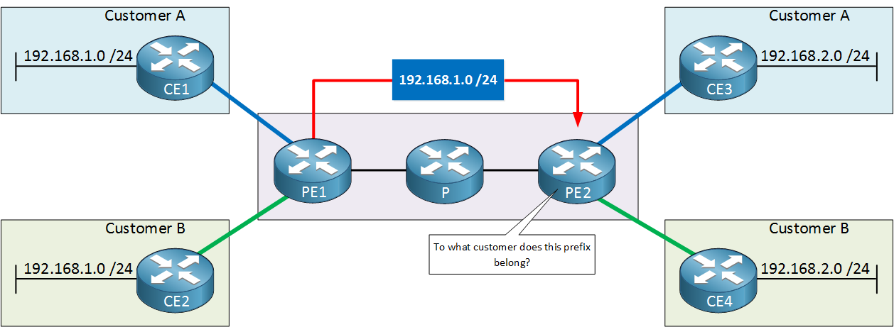
When PE1 advertises the 192.168.1.0/24 networks of CE1 and CE2 to PE2, they must somehow be made unique. This is done by prepending the RD to the route. So PE1 sends the following two updates to PE2:
- For Customer A, PE1 advertises the route to 192.168.1.0/24 with RD 123:10
- For Customer B, PE1 advertises the route to 192.168.1.0/24 with RD 123:20
Remember, uniqueness is achieved at PE1. This means that the MPLS service provider deals with RDs and not the customers themselves. RDs are invisible to the customers themselves.
Hmm, your phrase “at both ends of the MPLS tunnel” doesn’t really have meaning. The RD configured in PE1 is used for advertising a Customer 1 network in the CE1 router and making it unique (compared to the network from customer B in CE2. When PE2 receives this update, it will install it in its BGP table. The RD, in this sense, works in one direction.
Of course, PE2 will do the same thing in the opposite direction for networks belonging to Customer A connected to CE3, using another RD. This RD is independent of the original we used. It can actually be anything we want. It can be the same or different, it makes no difference because the advertising of a customer network in each direction (including the RD) is something independent and separate.
The RD is not a VRF-specific parameter, so you can configure multiple RDs within the same VRF and assign different prefixes to different VRFs. However, you should only do this if you need to maintain multiple routing tables for the same customer. If a single customer has overlapping address spaces, or have overlapping networks within the same customer network.
However, this could also complicate your network configuration and increase the chances of configuration errors. Additionally, it could lead to suboptimal routing decisions and affect the overall performance of your MPLS VPN network. Therefore, it’s essential to carefully evaluate your network requirements and use multiple RDs for a single VRF only when necessary.
BGP updates within an MPLS network are not tunneled over the MPLS network because the BGP control plane operates independently from the MPLS data plane. BGP is used to exchange routing information between PE routers while MPLS is used to forward customer data backets over the provider’s network. This is why in the Introduction to MPLS lesson, one of the prerequisites of the setup was to create a fully functional routing domain with full connectivity between the PE routers within the AS1234. This is done in the lesson using OSPF between all P and PE routers.
I hope this has been helpful!
Laz
Hello Vadim
In the lesson, Rene takes a step-by-step approach, and you can see that he initially creates the OSPF routing infrastructure within the AS 234, and then enables LDP. Once LDP is enabled, you can see that communication between the PE routers takes place with MPLS labels.
He then goes on to configure VRFs on the PE routers, which is where the RDs are RTs are configured to differentiate between different customers by creating the VPNv4 routes.
Finally, BGP is configured to exchange VPNv4 routes, thus enabling the Layer 3 VPN functionality of MPLS. So to answer your question, these are indeed the components that are needed to create the VPN functionality.
Yes that is correct. BGP itself and the configuration of VRFs, both take place in the control plane. This actually doesn’t use the tunneling of the MPLS network to operate but is necessary to create and maintain it.
To create an MPLS Layer 3 VPN infrastructure, yes VRFs are necessary. Theoretically, you can remove the VRF configurations from a particular PE, but you will run into the following problems:
- There will be no isolation between customer routing tables, and unpredictable routing conflicts can occur.
- You won’t be able to import or export customer routes at that PE router, which is a fundamental part of MPLS VPN.
- There will be no VPN label assignments taking place.
- You won’t be able to establish MP-BGP sessions since VRFs are needed on both ends of a BGP peering to successfully establish and exchange BGP routes.
You could remove all VRF configurations from all of your PEs. Still, then you are just reverting back to using only LDP over the MPLS network, eliminating the “VPN” component completely.
I hope this has been helpful!
Laz
Hi Laz,
Thank you for the detailed response, it makes sense. So, would I be right in saying that you can re-use RDs on different PEs, provided that the PE receiving the routes isn’t in a situation whereby there is no uniqueness? For example:
Not ok to re-use RD’s on PE1 and PE3:

Ok to reuse RD’s on PE1 and PE3:

Although I’m still unsure as to why BGP updates with source and destination IPs that can be label switched - for example, if I were to ping using the same destination and source IP addresses, it would be label switched - are not, unless there is a special condition for BGP control traffic.
Thanks.
Sam
Thanks, Laz. Yes, that was sure helpful. One note though - while to ‘send’ packets into VPN the VRF seems indeed is necessary, as otherwise one can’t ‘tag’ traffic with particular RD (seems to assign RD on CISCO one has to be in some VRF), the other end of the tunnel does not have to end in VRF. Traffic is already labeled with RD so it is unique and seems ‘seeing’ RD tag is enough for MPLS to react and encapsulate that packet. Meaning VPN should be created between source VRF and global vrf on destination and traffic will flow labeled switched. Global should not be able to send traffic into VPN though, since it does not have means to assign RD. However, it should be able to pass traffic into VPN if it already has packets tagged with RD, like when another router with VRF sends traffic to it. So seems two sites with configured VRFs can talk to each other by passing VPN packets through intermediary router that only has global vrf. The reason question arose is that sometime ago I saw something like that, where VRF based router talked to router that did not have any VRFs, over MPLS. Did not really understand it then nor gave it much thought. Until started to look deeper into MPLS and felt that maybe now I should be able to understand it. I hope to find some time and set up it in the lab but I think maybe my understanding is correct.
Hello Samir
It is important to note that RDs are locally significant to the PE router and are used to differentiate routes within the same router. Therefore, using the same RD on different PE routers can work in some instances, as long as the VPN-IPv4 or VPN-IPv6 addresses remain unique within the network.
For example, if you have two PE routers, each serving different VPN customers that do not have overlapping IP address spaces, you can use the same RD on both routers without causing routing issues. In this scenario, even though the RDs are the same, the VPN-IPv4 or VPN-IPv6 addresses will remain unique because the IP prefixes for each customer are different.
In my previous post I had suggested that you can use the same RD in the opposite direction. Although that would work in the specific topology, where there are only two customer A sites, it would not make sense if you had more sites, because the RD and IPv4 addresses must be unique when arriving at each individual PE router. Similarly, in your example topologies you would be correct to reuse RDs in the situations you state, but these are very specific situations. If you add another customer A site somewhere the reuse of RDs would no longer be unique.
For this reason, to avoid potential issues and ensure proper routing and isolation, it is generally recommended to use unique RDs for different VPNs in an MPLS Layer 3 VPN environment.
By definition, the BGP control plane operates independently from the MPLS data plane. It’s a chicken and egg problem. You can’t use BGP information exchanged via label switching to operate and configure MPLS Layer 3 VPNs. It’s just the way in which all of these various technologies (BGP, OSPF, MPLS, VPNv4) interact with each other by design.
I hope this has been helpful!
Laz
1 Like
Hello Vadim
What you are describing is traffic in one direction. If we look at this topology for example, you are correct, any traffic sent from CE1, is tagged with the appropriate RD at PE1, and when it reaches PE2, you don’t need an RD configured there to determine where that traffic goes. Theoretically, you don’t even need a VRF… except for one small detail…

As shown in the diagram, you do need an RT so that the PE2 router knows to which VRF VPNv4 routes must be imported to, and exported from. In order to configure the RT, you need to configure a corresponding VRF.
So theoretically, for traffic in one direction, you don’t need a VRF, however, you must remember that we still need an RT to be configured, which requires a VRF. Additionally, in order to accommodate traffic going in the other direction, you need to configure the same type of VRF/RD setup as you did on PE1 for return traffic. Does that make sense?
I believe that labbing such a setup will allow you to experiment with the various options, and determine what works and what doesn’t. Also, you mentioned that you “saw something like this” sometime ago. Can you share with us the particular example, and let us know if this was a production network?
I hope this has been helpful!
Laz
Thanks, Laz. So ordering my thoughts and coming from actual practical encounters, here is the scenario where what I described might be advantageous and would work.
Its a little difficult for me to produce the pictures so I just use the one you presented and hope I can describe the scenario in reasonably comprehending way. Here is the carrier network, like the one on your picture. But now we expand it, to make more ‘real world’, where we have hundreds of PE routers (though maybe only couple dozen of P routers). Most, if not all, PE routers have dozens of the same VRFs to allow clients to communicate from different locations over carrier cloud. So each PE router needs to peer to each other PE router, creating peer config including vpnv4, to all other routers having same VRFs/clients. Thats something like (n-1)n connections/configurations per VRF or (n-1)nX configuration pieces (where X is a number of vrf on each router). I have enemies and I hope all of them would work at this carrier as network engineers. If I happen to work at one and Im lazy I can think of the following set up (in a simplest case, I say there is only one P router, in reality there could be a dozen). So I configure each PE router to peer ONLY with P router and ONLY with its Global VRF. In which case I get something like nX-1 connections to configure, with P router now acting as a hub for VPNv4 traffic. It should work because P router will receive RD tagged packets and will not strip them (it does not have configuration for that) but it should read the whole address and direct it according to labels forwarding table, that is to appropriate PEs with appropriate destination VRFs, in both directions.
It is something that indeed I encountered on our network and I think/hope I understand now the logic and mechanics behind it, not to mentioned that it definitely works - I can see it in production. Sure, there are more than 1 P router but still much less than PEs. And if network is large and there are different teams supporting PE/CE side and core then its additional benefits as core team only have dozen routers to configure, all in the same manner.
Hello Vadim
This is a nice way to look at various scenarios and see their benefits and drawbacks in each case. Once again, as in another one of your posts, trying to visualize the topology from text can be challenging, but your description, as far as I can understand, makes sense, and the advantages you cite are also valid.
For certain situations, this setup may indeed be the best, and since you have seen it in practice, there is no doubt about it. There are some considerations you should also take into account when looking at this particular setup.
The first is scalability. Although the solution you describe is scalable as far as configurations go, it is not scalable as far as the infrastructure goes. As the number of PE routers grows, the P router acting as a hub will need to handle more connections, which could become a bottleneck and limit the scalability of the network.
The second has to do with resilience. Having a single P router act as a hub for VPNv4 traffic introduces a single point of failure.
The third has to do with traffic engineering. By forcing all VPNv4 traffic to pass through a single P router, you lose the ability to optimize traffic flow and load balancing across multiple paths in the network.
If these are acceptable limitations for the particular implementation, then by all means, you can enjoy the benefits you describe. But these should be considered when making the final decision.
I hope this has been helpful!
Laz
Thanks, Laz. To note: Our network is not the largest one there is but still very large. P router in question is ASR9000 and so far its not overwhelmed - part of it is the fact that since its not running VRFs the processing is much lower than at PE routers and even in absence of peering with PEs still all the PEs traffic will be coming through it. So it seems its not a huge difference in processing/memory consumption. Redundancy is not compromised since while Im talking about logically P router, in reality each is a redundant pair, of course, so its ‘routers’. And if both are down, there is an alternate, if less optimal, path through other site. Again, should not be much different from the case when traffic simply passes/switched through the routers vs having BGP peering on them. RE traffic engineering - again, its not a single P router, the peering can be (and is) done to several P routers located in different sites, so there is always path to destination which is based on BGP calculations. But it is understood that there is always some compromise, nothing is ideal. Starting with some engineers, like me, who can be somewhat dumbfounded when encounter configuration that is not a textbook and have to scratch their head and spend additional time figuring out what exactly this configuration is doing. Definitely, takes time and effort, which translates to ‘lost’ productivity.
But Im glad that finally I got it - certainly adds to better understanding of the whole thing, how mp-bgp/mpls works.
As always, thanks for very useful discussion.
Hello Vadim
I agree such discussions are valuable as they help us fully understand each scenario’s implications, benefits, and drawbacks and allow us to evaluate and balance what risks and benefits we want for our particular topology.
Great to discuss with you, as always!
Laz
Hi Rene, I do have a question , why was I not able to ping the 5.5.5.5 loopback of CE2 from the PE1, but of course you can ping it from CE1 ?
Thanks.
Hello Soufiane
This is normal behavior and is done by design. Typically, an ISP that delivers MPLS services does not want customer devices and networks to have direct communication with their PE and P routers. For more information on why this is the case, take a look at this NetworkLessons note on the topic.
If you have any further questions, feel free to let us know!
I hope this has been helpful!
Laz
Hello, everyone!
What exactly defines a VPN, please?
I originally thought that a tunnel and a VPN were the same. Or to put this better, isn’t VPN a network/connection that we run over a tunnel?
So in the case of normal MPLS where we used only the mpls ip command, that wasn’t considered a VPN yet? While in this current scenario with the VRFs and RDs/RTs, it is?
Is this because each customer has their own dedicated and private paths to reach eachother? If we configure VRFs, RDs/RTs and so on, each customer is effectively isolated form the rest which makes it a private connection while in normal MPLS, all customers could reach eachother, there was no separation and isolation of customer traffic.
So is it right to say that just pure MPLS without any VRFs and so on configured isn’t a tunneling mechanism, but when we issue the necessary configuration (VRFs, RDs/RTs, MP-BGP), then we gain path abstraction which effectively causes MPLS to become a tunnel and the connection a VPN?
If that’s the case, then the main two combinations which create a tunnel are Encapsulation + Path Abstraction/Traffic isolation, right?
Thank you.
Kind regards,
David
Hello David
A VPN is a technology that creates a secure and encrypted connection over a less secure network, such as the Internet. It’s like a protected tunnel through which your online traffic can pass undisturbed, away from the prying eyes of hackers, your ISP, the government, and even the websites you visit. VPNs can be deployed in various forms, such as site-to-site, host-based, or even via a subscription-based VPN provider, which creates a VPN between your device and its servers, which then act as a proxy for your communications.
In the context of MPLS, a VPN can be thought of as a ‘pseudo-wire’ that exists in an MPLS network. This pseudo-wire is able to transport payload traffic of various types and segments, each isolated from each other. This is where your understanding of a VPN as a network/connection running over a tunnel comes in.
The mpls ip command simply enables MPLS on the interface, but does not make it a VPN. The VPN comes into play when we start using VRFs and RDs/RTs. These are used to segregate customer traffic, making each customer’s traffic private from others - hence the term VPN.
In a normal MPLS network without VRFs, RDs/RTs, all customer traffic would indeed be in the same routing instance, which would not provide the necessary separation and isolation for it to be considered a VPN.
So, to answer your question, yes, pure MPLS without any VRFs, RDs/RTs is not a tunneling mechanism. But when we add these configurations, we gain the path abstraction and traffic isolation you mentioned, effectively turning it into a VPN.
The two main components that create a tunnel, as you correctly identified, are encapsulation and path abstraction/traffic isolation.
However, there are two additional pieces of information that must be addressed:
First, such a VPN in the context of MPLS does not apply any form of security, which is traditionally associated with VPNs. If you want to ensure an encrypted MPLS L3 VPN implementation, you can use an option such as MPLS over FlexVPN, but there are others.
The second is that MPLS L3 VPNs use what are known as VPNv4 and VPNv6 routes. In the context of BGP and MPLS these terms refer to the BGP address family used to carry IPv4 and IPv6 prefixes over MPLS-based VPNs. So the term VPN in this context is a well-defined terminology for MPLS and means something very specific.
I hope this has been helpful!
Laz