Hi MPLS team,
I understood MPLS L3 VPN concept along with your brief example.
However, I have one doubt based on your example “MPLS Layer 3 VPN Configuration” inwhich VPN label has been advertised by PE1 and PE2. This VPN label is same number or PE1 and PE2 advertised different number..? you explained PE1 side but PE2 side through cli was not mentioned.
similarly 6VPE you have mentioned same VPN label for PE1 and PE2. So VPN label for PE1 and PE2 are same number..? or different number that i am confusing..
Please show appropriate cli for PE1 and PE2 in your explanation.
In an MPLS L3 VPN, the VPN label is not the same for PE1 and PE2. Each PE router generates its own VPN labels for the VPN routes it advertises to its peers. However, when these labels traverse the MPLS network, they remain the same throughout the journey of the packet. When the packet arrives at PE2, you will see that it will have the same VPNv4 label.
This can be seen in the lesson, if you take a look at the output from the show mpls forwarding-table command on PE2, you will see the local label marked as 19, which is the same value as the VPNv4 label that was originally sent from PE1.
The VPN label used to reference a particular customer network remains the same throughout the communication. For example, in the 6VPE lesson, he PE2 router will assign a VPN label of 19 to the 2001:DB8:5:5::5/128 network (its own customer network) and will advertise that throughout the topology. PE1 learnes about that, and this is why in the output of the show bgp ipv6 unicast command, you can see a label value of 19.
When PE1 advertises its VPN label for its customer network of 2001:DB8:1:1::1/128, it too assigns the label number of 19, but this is independent of that assigned by PE2 to its customer network. The fact that the numbers are the same may be what is confusing. This is independent and can be any number. But these don’t cause any problems if they are the same because they are used in completely different contexts. Does that make sense?
I tried to read all the questions but didn’t find any answer. I hop you didn’t already replied.
We are configuring a BGP session in the IPv4 family between PE1 and CE1. How can the routes learned from this AF appear in the VPNv4 AF? Is there a kinf of automatic redistribution between the 2 AFs?
In the context of MPLS VPN on Cisco IOS devices, the redistribution of routes from the CE-facing VRF (vrf CUSTOMER) into the MPLS core (VPNv4 address family) for advertisement to other PE routers via iBGP is handled automatically when the following conditions are met:
VRF Configuration: Routes learned on a VRF interface from a CE are automatically placed into the VRF routing table for that VRF.
BGP Configuration: The PE router has BGP configured with the address-family ipv4 vrf CUSTOMER context, which specifies how to handle IPv4 routes within that VRF.
Route Target Configuration: The VRF is configured with Route Targets that control the import and export of routes to and from the VPNv4 routing table.
No additional redistribution commands need to be applied in order for those routes to appear in the VPNv4 address family. Does that make sense?
Thanks for giving a solid insight into L3 VPN configuration, really helps me with my CCNP Service Provider studies. My only question is: Will you also cover concepts and implementation of MPLS L3 Multicast VPN’s some time in the future? I surfed through many YouTube tutorials, Cisco press whitepapers, configuration guides, but the presentation of the topic was a bit vague and still leaves me with a lot of uncertainty. But your style of explanation always clarifies things much better.
It’s great to hear that you find Rene’s content useful, clear, and understandable. It is true that Rene doesn’t have a more detailed coverage of MPLS L3 Multicast VPNs, however, if you like you can make a suggestion for such a lesson at the following Member Ideas page:
You may find that others have made similar suggestions and you can add your voice to theirs. Rene chooses to create new content based on the most popular topics as they appear there.
I have few questions.
1st: why can’t we ping from ce1 to ce2 without source loop back 0, and if I don’t want to use source is that possible?
2nd: If I added to PCs at CE sites, will they be able to ping each other or do I need to make
changes.
3rd: Why I can’t Ping CE2 from PE1 even though I’m getting CE2 5.5.5.5 in routes, but I can ping CE1 4.4.4.4.
      4.0.0.0/32 is subnetted, 1 subnets
B        4.4.4.4 [20/0] via 192.168.1.4, 00:36:44
      5.0.0.0/32 is subnetted, 1 subnets
B        5.5.5.5 [200/0] via 3.3.3.3, 00:23:45
      100.0.0.0/24 is subnetted, 1 subnets
B        100.100.100.0 [20/0] via 192.168.1.4, 00:08:13
      192.168.1.0/24 is variably subnetted, 2 subnets, 2 masks
C        192.168.1.0/24 is directly connected, GigabitEthernet2/0
L        192.168.1.1/32 is directly connected, GigabitEthernet2/0
B     200.200.200.0/24 [200/0] via 3.3.3.3, 00:07:30


R1#ping vrf RED 4.4.4.4
Type escape sequence to abort.
Sending 5, 100-byte ICMP Echos to 4.4.4.4, timeout is 2 seconds:
!!!!!
Success rate is 100 percent (5/5), round-trip min/avg/max = 36/66/84 ms
R1#ping vrf RED 5.5.5.5
Type escape sequence to abort.
Sending 5, 100-byte ICMP Echos to 5.5.5.5, timeout is 2 seconds:
.....
Success rate is 0 percent (0/5)
MPLS is designed to allow networks behind the CEs to communicate with each other. Communication of the CE routers directly from their MPLS-facing interfaces is unnecessary to make the whole thing work. Take a look at this NetworkLessons note on the topic. You can make CEs communicate with each other directly by injecting the networks between the CE and PE routers into the MPLS domain, but that would serve no purpose since CEs don’t need to communicate directly.
If you added PCs behind each CE, they would be able to reach each other. Much like the pinging from loopback to loopack, from PC to PCE will work correctly.
Hello Rene,
This is a very informative and straightforward post. I have a question that perhaps you can answer. I would like to connect OSPF sites using MPLS VPNs. Do you have a lesson for this specific topic? Can I just use this configuration and just add OSPF? Thanks
It describes an MPLS Layer 3 VPN with OSPF running between the CE and PE routers to share the local routes of each customer location. If you have any further questions, let us know!
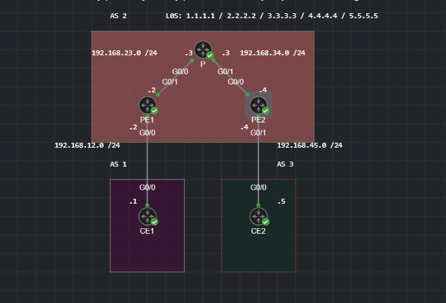
For some reason in the topology below I can ping the ebgp neighbors from AS1 to AS3 but not their loopbacks. I also cannot ping the ebgp neighbors from any of the IGP routers except the ones that are directly connected. I am not sure if there is a command I am missing or something I tried to follow the guideline in the eBGP post. Is it possible to get some guidance or suggestions on what I may doing wrong?
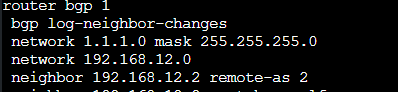
But here I can reach it from AS3, I am confused what is causing this behavior. I am also not sure why when I do the network 192.168.12.0 mask 255.255.255.0 command it just shows as network 192.168.12.0
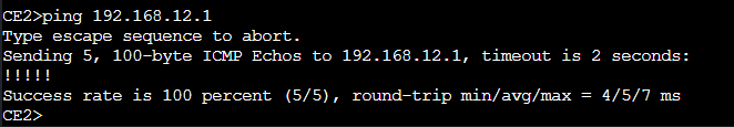
The behavior you are seeing is normal. You haven’t configured anything wrong. The purpose of such an implementation is to allow the remote networks to communicate with each other. You should be able to ping the 1.1.1.1 network from the 5.5.5.5 network using a ping on CE2 that uses the loopback as the source of the ping. Similarly, you should be able to ping the 5.5.5.5 network from 1.1.1.1, again using the local loopack as the source.
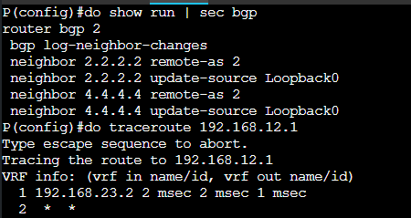
There is no requirement that the CE/PE/P routers should be able to ping each other. Indeed, under normal circumstances, the CE1 router should not be able to ping the Ge0/0 interface of the CE2 router or visa versa. See this NetworkLessons notes below:
The same is true about the direct communication between P routers and the CE router networks. The role of the backbone network (PE and P routers) are to ensure that the next hop IP issued by BGP is reachable. That’s all, and that’s part of the benefits of MPLS. MPLS itself doesn’t need to know how to reach all networks or all routers, it just needs to be able to reach the next hop to make it work.
If there is no mask showing up that means that the classful subnet mask is being used. The classful subnet mask for this particular address is indeed 255.255.255.0. If you issue a network command with a mask that is different from the classful one, then it will appear in the running configuration.
Thank you as always for the quick and great responses. I did not know that it was not a requirement that every single router in that topology has to be able to ping each other. I did use the topology from that but I did not configure the L3VPN because I just wanted to practice configuring BGP. What is the reason for this behavior with the routers? Is it just because say an ISP for example doesn’t need to know how to exactly reach every router (For example P doesn’t need to know how to reach CE1 it just cares about the label it receives)? This would probably make the routing table huge which is why we use MPLS to reduce overhead within the network. Am I thinking correctly
Yes that’s exactly it. The purpose of the MPLS backbone is to convey packets using labels. It doesn’t need to know about the networks found behind the CE routers.
Remember the ultimate goal is to allow customer networks to communicate. So you should be able to ping from one customer network to another customer network. MPLS core routers will never need to know the customer networks as they will never need to communicate directly with them.
Thanks for the explanation. However, I cannot understand how the problem in the Data Plane is solved in detail.
CE router sends an IP Packet with a destination to the CE on the other site, so it uses its FIB built from the IP routing table and the next hop is the PE router, as the route advertisement stated.
The PE router receives the packet on the interface associated to the VRF for the customer, so in order to forward the incoming packet it will use the FIB for that VRF ?? (derived CEF Table as Cisco specifies in its documentation) and the next hop will be the Loopback Interface of the other PE router.
However, the VRF table doesn’t receive the route to the other PE Loopback Interface, so how is the packet going to be forwarded? Rene also proved this with the display of the show ip route vrf CE1 and the next hop address is not founded there, is in the GRT.
I know that the packet is forwarded, but how? Isn’t the derived CEF table for the VRF built only with the VRF routing table and information? How does the packet don’t get dropped when the next hop address is not found in the VRF routing table?
That is correct. The CUSTOMER VRF in PE1 does not have the 4.4.4.4 next hop address in the routing table. However, the global routing table does have the destination, and this can be seen from the output of the show ip route 4.4.4.4 command that Rene uses immediately after.
And Rene explains it this way:
This is an exception for VPNv4, based on the transport label the router knows to use the global routing table to figure out where 4.4.4.4/32 is. Here’s a good way to see both labels and the logic of the PE1 router how it will reach the next hop:
So VPNv4 knows to use the global routing table to find the 4.4.4.4 based on the transport label. Because within the CUSTOMER VRF, to reach our ultimate destination of 5.5.5.5, the information about the label (17) is there, and the next hop to reach the label is also there.
Remember that within the MPLS topology when using VPNv4, it’s not IP routing that is being used, but a label switching overlay. So what PE1 will do is, it won’t look for the 4.4.4.4 next hop, but will look for the MPLS label that corresponds to the destination. That’s why it sees the next hop of 192.168.23.3 for label 17 to get to 5.5.5.5, and it knows where to send it. Does that make sense?
As my understanding. if we added another customer to PE2 and named its vrf Cust2 and inside of this vrf we exported rt 1:1. will Cust CE1 be able to communicate with him?
The communication between Cust CE1 and the new customer on PE2 (Cust2) depends on the import and export route targets for their respective VRFs.
If you have exported route target (RT) 1:1 in CUST2 VRF, you also need to import RT 1:1 in the CUST1 VRF for them to be able to communicate. This is because the export RT of one VRF should match the import RT of the other VRF for routes to be exchanged between them.
So you will have to make sure that you have set up the import RT in Cust CE1’s VRF to match the export RT of Cust2, in order for them to communicate.
So the communication is possible but it depends on the correct configuration of import and export RTs.