This topic is to discuss the following lesson:
Hi,
Thank you for explaining how the MPLS over FlexVPN work.
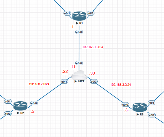
I followed the steps and created a lab but the NHRP is not initiating and I couldn’t receive any routes from the spokes (I made some modifications in the ikev2 profile using the ip addresses instead of the fqdn). Following my config :
Hub:
vrf definition CUSTA
rd 1:1
!
address-family ipv4
route-target export 1:1
route-target import 1:1
exit-address-family
!
aaa new-model
aaa authorization network FLEXVPN_LOCAL local
!
crypto ikev2 authorization policy IKEV2_AUTHORIZATION
route set interface
crypto ikev2 keyring KEYRING
peer SPOKES
address 0.0.0.0 0.0.0.0
pre-shared-key local cisco123
pre-shared-key remote cisco123
!
crypto ikev2 profile IKEV2_PROFILE
match identity remote any
identity local address 192.168.1.1
authentication remote pre-share
authentication local pre-share
keyring local KEYRING
aaa authorization group psk list FLEXVPN_LOCAL IKEV2_AUTHORIZATION
virtual-template 1
crypto ipsec profile IPSEC_PROFILE
set ikev2-profile IKEV2_PROFILE
!
interface Loopback0
ip address 172.16.1.1 255.255.255.255
!
interface Ethernet0/0
ip address 192.168.1.1 255.255.255.0
duplex auto
!
interface Virtual-Template1 type tunnel
ip unnumbered Loopback0
ip nhrp network-id 1
ip nhrp redirect
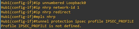
mpls nhrp
tunnel protection ipsec profile IPSEC_PROFILE
!
router bgp 1
bgp router-id 172.16.1.1
bgp log-neighbor-changes
bgp listen range 172.16.1.0/24 peer-group FLEXVPN_SPOKES
neighbor FLEXVPN_SPOKES peer-group
neighbor FLEXVPN_SPOKES remote-as 1
neighbor FLEXVPN_SPOKES transport connection-mode passive
neighbor FLEXVPN_SPOKES update-source Loopback0
!
address-family ipv4
neighbor FLEXVPN_SPOKES activate
neighbor FLEXVPN_SPOKES send-community both
exit-address-family
!
address-family ipv4 vrf CUSTA
network 10.0.0.0
exit-address-family
!
ip route 192.168.2.0 255.255.255.0 192.168.1.11
ip route 192.168.3.0 255.255.255.0 192.168.1.11
ip route vrf CUSTA 10.0.0.0 255.0.0.0 Null0
Spoke:
vrf definition CUSTA
 rd 1:1
 !
 address-family ipv4
  route-target export 1:1
  route-target import 1:1
 exit-address-family
!
aaa new-model
aaa authorization network FLEXVPN_LOCAL local
!
crypto ikev2 authorization policy IKEV2_AUTHORIZATION
 route set interface
crypto ikev2 keyring KEYRING
 peer HUB
  address 192.168.1.1
  pre-shared-key local cisco123
  pre-shared-key remote cisco123
 !
 peer SPOKE3
  address 192.168.3.3
  pre-shared-key local cisco123
  pre-shared-key remote cisco123
 !
crypto ikev2 profile IKEV2_PROFILE
 match identity remote address 192.168.1.1 255.255.255.255
 match identity remote address 192.168.3.3 255.255.255.255
 identity local address 192.168.2.2
 authentication remote pre-share
 authentication local pre-share
 keyring local KEYRING
 aaa authorization group psk list FLEXVPN_LOCAL IKEV2_AUTHORIZATION
crypto ipsec profile IPSEC_PROFILE
 set ikev2-profile IKEV2_PROFILE
!
interface Ethernet0/0
 ip address 192.168.2.2 255.255.255.0
 duplex auto
!
interface Ethernet0/1
 vrf forwarding CUSTA
 ip address 10.1.2.1 255.255.255.0
 duplex auto
!
interface Virtual-Template1 type tunnel
 ip unnumbered Loopback0
 ip nhrp network-id 1
 ip nhrp shortcut virtual-template 1
 mpls nhrp
 tunnel source Ethernet0/0
 tunnel protection ipsec profile IPSEC_PROFILE
!
router bgp 1
 bgp router-id 2.2.2.2
 bgp log-neighbor-changes
 neighbor 172.16.1.1 remote-as 1
 neighbor 172.16.1.1 update-source Loopback0
 !
 address-family vpnv4
  neighbor 172.16.1.1 activate
  neighbor 172.16.1.1 send-community both
 exit-address-family
 !
 address-family ipv4 vrf CUSTA
  redistribute connected
 exit-address-family
!
ip route 192.168.1.0 255.255.255.0 192.168.2.22
Thank you in advance for your comments.
Hello Mourad
Looking over your configs initially the only thing that needs modification is the addition of another static route on your spoke router to allow it to communicate with the subnet of the other spoke. Specifically:
ip route 192.168.3.0 255.255.255.0 192.168.2.22
This way communication between spokes can be successful. In your topology, each router is in a different subnet, while in the lesson, they’re in the same subnet, so this additional command is necessary. Note that you will have to enter the appropriate static route on the other spoke router as well.
Now NHRP in this particular case is used for learning spoke-to-spoke routes. Note in the lesson that the routing table of the spoke routers displays the route learned from the other spoke as an NHRP route. Resolving the routing problem mentioned before should bring up the NHRP operation. Give it a try and let us know how you get along.
I hope this has been helpful!
Laz
Hello Rene/Laz,
I was trying to build this lab in GNS3. Can you please help how to design lab using GNS3
Thanks,
Bhupesh
Hello Bhupesh
To reproduce the topology in this lesson, simply follow the instructions for the configuration. There’s no specialized configuration necessary, whether you use GNS3, or CML, or EVE-NG. Can you share with us the specific problems that you are facing so that we can help you resolve them specifically?
I hope this has been helpful!
Laz
I have a problem when configuring tunnel protection ipsec profile IPSEC_PROFILE output Profile IPSEC_PROFILE is not defined. I’m using a Cisco IOSv 15.6(1)T router. Before using this router, I tried using a Cisco IOSv 15.9(3)M2 router, but it didn’t support “crypto” configurations. I need a solution to solve this problem. Please help me sir.
Hello Irvan
Hmm, that’s a bit strange for an IOSv software. However, it has been known to happen.
I went into my CML and booted up a router running a similar version to yours. Take a look:
R2#show version
Cisco IOS Software, IOSv Software (VIOS-ADVENTERPRISEK9-M), Version 15.9(3)M4, RELEASE SOFTWARE (fc3)
Technical Support: http://www.cisco.com/techsupport
Copyright (c) 1986-2021 by Cisco Systems, Inc.
Compiled Wed 04-Aug-21 08:13 by mcpre


ROM: Bootstrap program is IOSv

R2 uptime is 4 minutes
System returned to ROM by reload
System image file is "flash0:/vios-adventerprisek9-m"
Last reload reason: Unknown reason


This product contains cryptographic features and is subject to United
States and local country laws governing import, export, transfer and
use. Delivery of Cisco cryptographic products does not imply
third-party authority to import, export, distribute or use encryption.
Importers, exporters, distributors and users are responsible for
compliance with U.S. and local country laws. By using this product you
agree to comply with applicable laws and regulations. If you are unable
to comply with U.S. and local laws, return this product immediately.

A summary of U.S. laws governing Cisco cryptographic products may be found at:
http://www.cisco.com/wwl/export/crypto/tool/stqrg.html

If you require further assistance please contact us by sending email to
export@cisco.com.

Cisco IOSv (revision 1.0) with  with 484577K/37888K bytes of memory.
Processor board ID 946CLDZMQRQ1FICH2EYSF
2 Gigabit Ethernet interfaces
DRAM configuration is 72 bits wide with parity disabled.
256K bytes of non-volatile configuration memory.
2097152K bytes of ATA System CompactFlash 0 (Read/Write)
0K bytes of ATA CompactFlash 1 (Read/Write)
11217K bytes of ATA CompactFlash 2 (Read/Write)
0K bytes of ATA CompactFlash 3 (Read/Write)


Configuration register is 0x0
Now one piece of information that is very important here to see if the crypto features are supported, is this:
System image file is "flash0:/vios-adventerprisek9-m"
Notice the “k9” at the end of the image file name. Take a look at the output of your show version command and see if that’s there. I’m willing to bet that it’s not.
But if it is, let us know and we’ll see if we can help you troubleshoot the problem further.
I hope this has been helpful!
Laz
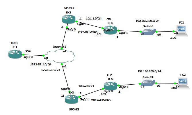
Okay now I’ve successfully configured MPLS over FlexVPN according to what you exemplified. Routers CE1 and CE2 can be pinged. However, I would like to add PC1 after the CE1 router. And PC2 after CE2 router. What configurations do I need for PC1 and PC2 to be connected?
I need your help sir, what configurations are needed on the CE router and PC so that PC1 and PC2 can be connected to each other? The network topology and configuration I’m using is exactly what you taught me. I added ip at int0/1 on Router CE1 192.168.100.1/24 and at int0/1 on Router CE2 192.168.200.1/24.
I am using IP on PC1 192.168.100.100/24 with gateway 192.168.100.1. And use IP on PC2 192.168.200.200/24 with gateway 192.168.200.1. The problem is that both PC1 and PC2 cannot be connected to each other
Hello Irvan
Like standard MPLS, MPLS over FlexVPN allows the address spaces of multiple customers to be routed over an MPLS infrastructure using different VRFs. This allows customer IP address spaces to overlap. The actual addresses for each customer that can be routed across the infrastructure are advertised by the spoke routers (or PE routers in MPLS parlance).
For example, in this lesson, spoke 1 has VRF CUSTOMER defined as the address space configured on Gi0/1. This, in turn, is redistributed into BGP using the redistribute connected command. So the MPLS infrastructure learns of that customer address space and can route traffic to and from that subnet successfully. Spoke 2 is similarly configured with its CUSTOMER VRF as well.
Now, if you add the PCs and the addresses as you have done, the MPLS infrastructure knows nothing about the 192.168.100.0/24 and 192.168.200.0/24 networks. CE1 will forward such packets because it has a default gateway set up. But when spoke 1 receives such a packet, it doesn’t recognize the destination address and will drop the packet.
The same happens for packets sent from PC2.
If you want the networks behind the CE routers to be routable over the MPLS infrastructure, you must advertise those over the MPLS infrastructure as well. To do this, you must configure the CE routers to advertise their internal routes to the spoke routers. Currently in this lesson, there is no such route advertisements configured.
To see how this can be done, take a look at how the CE routers are sharing their networks in the following MPLS configuration. The config should be the same for both standard MPLS and for MPLS over FlexVPN.
I hope this has been helpful!
Laz
where can i find the Qos course for MPLS ?
(same question but SR for MPLS too)
Hello Mehdi
We don’t have lessons that focus specifically on QoS implementations on an MPLS network. However, we do have a whole series of lessons that Rene recently added on Traffic Engineering, which is related.
Similarly, we don’t have any content about Segment Routing in the context of MPLS. However, take a look at the MPLS course below to see what lessons about MPLS do exist on the site.
If you have suggestions for future courses and lessons to be created by Rene, please feel free to go to the Member Ideas page below to make your suggestions. You may find that others have suggested similar material, and you can add your voice to theirs.
I hope this has been helpful!
Laz