MTU Troubleshooting on Cisco IOS

Hello John

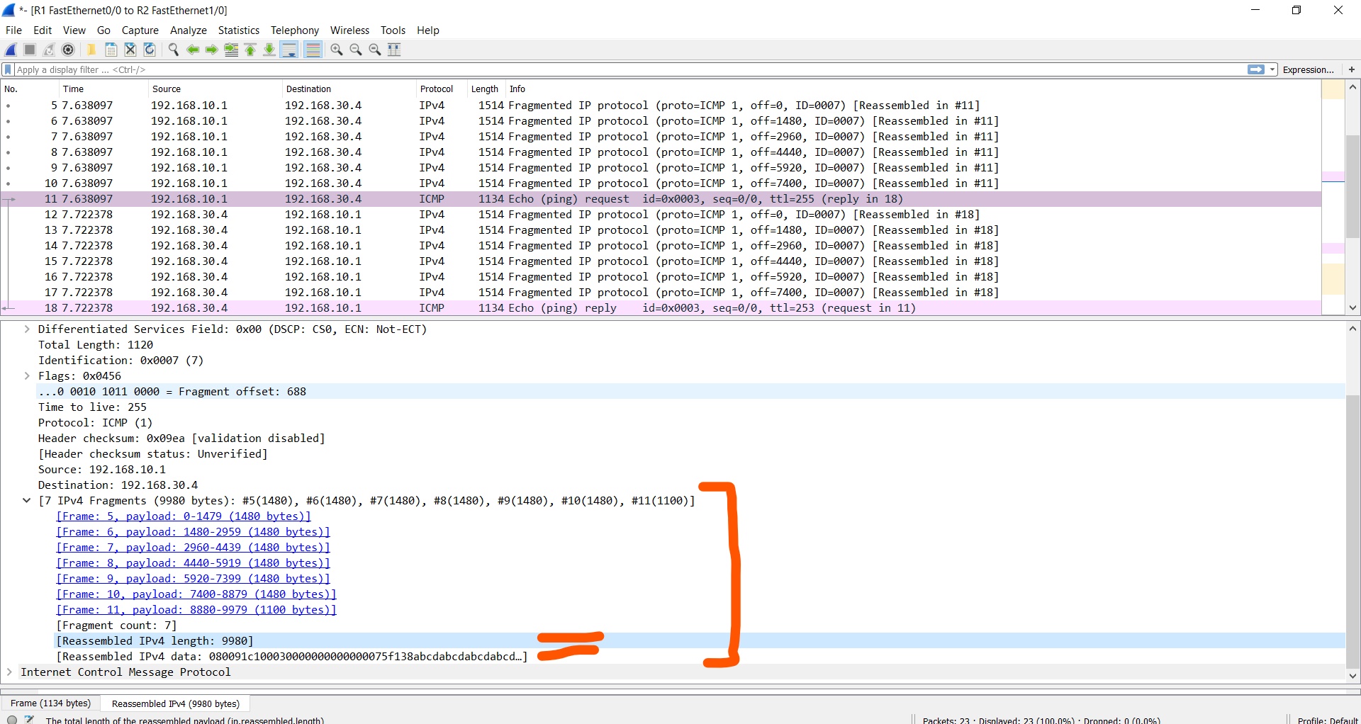
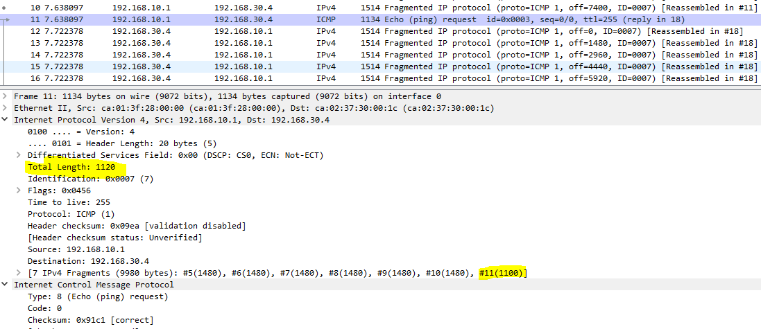
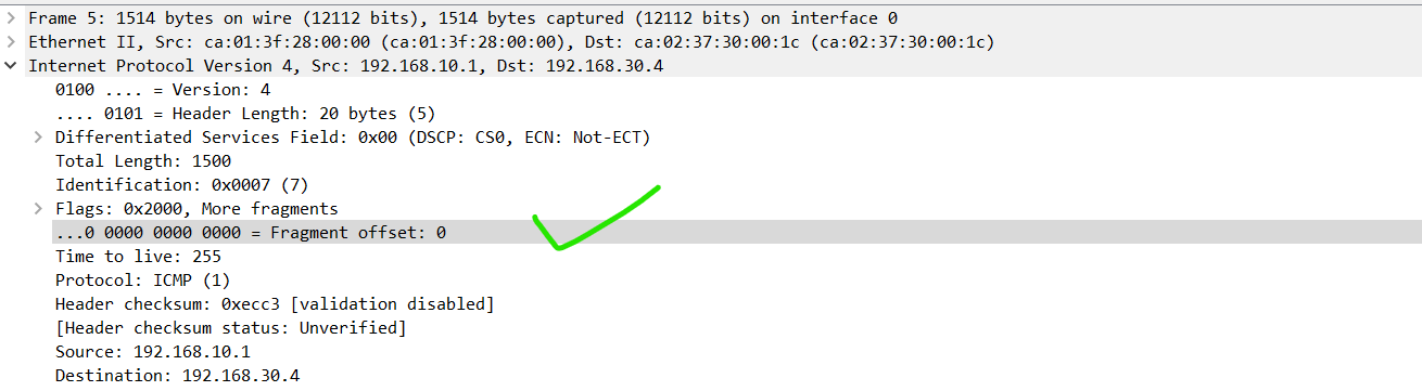
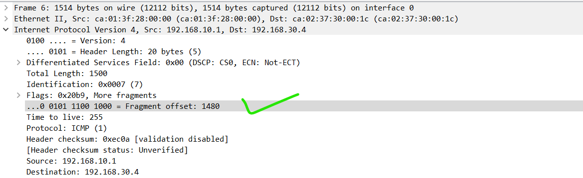
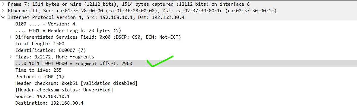
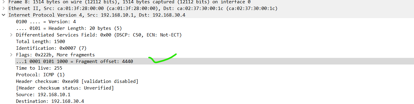
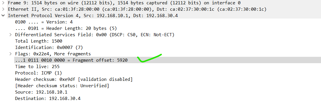
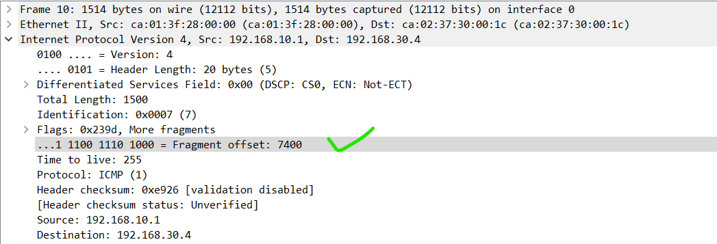
I think the important thing here to note is that all of the MTU configs affect encapsulation. So if there is a segment with a size larger than the IP MTU, then that segment will be fragmented into multiple IP packets during encapsulation from L4 to L3. This would actually occur at the host that is sending the data. (routers do not de-encapsulate PDUs to layer 4 unless they are functioning as deep inspection firewalls, but I digress).

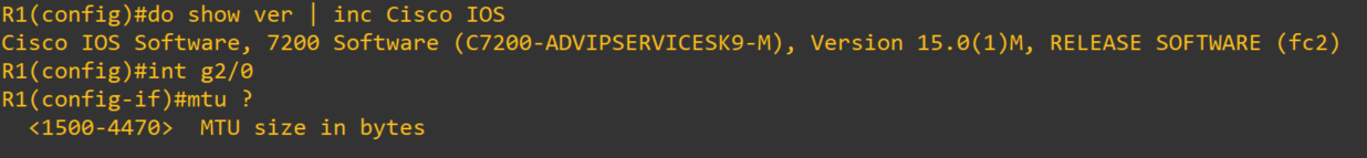
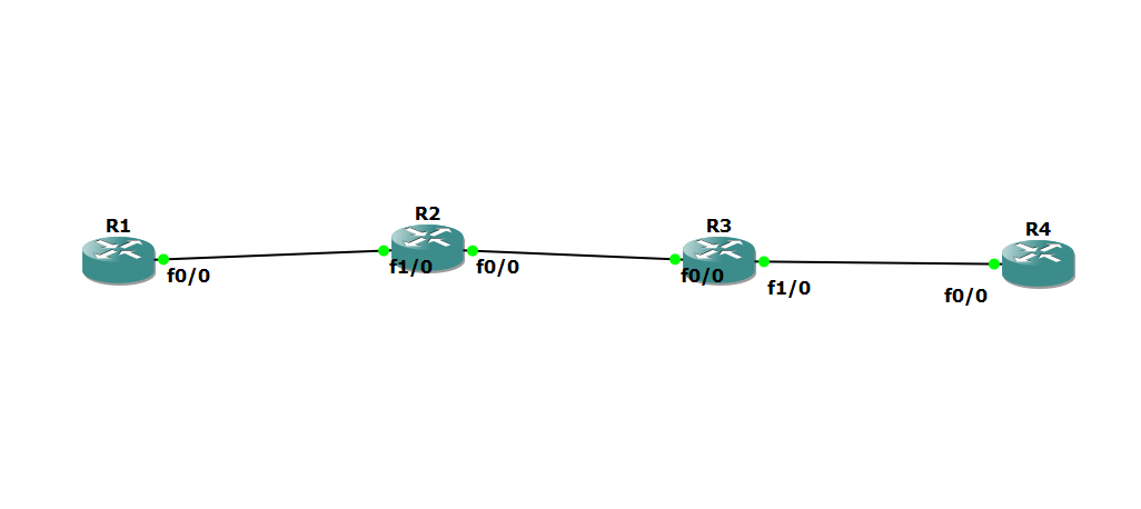
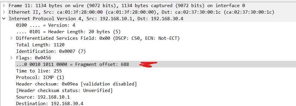
If a packet comes in to a router and is deencapsulated, its destination IP address is checked, and the exit interface is determined, then the packet will be reencapsulated from L3 to L2. It is at this point that the IP MTU and the Interface MTU are examined. If the interface MTU is too small for the size of the packet, it will be fragmented and encapsulated into two frames unless the DF bit is set. I don’t know of any other scenario in which fragmentation will not occur when the DF bit is not set.

I hope this has been helpful!

Laz

1 Like

Hi Rene and staff,
this is a very good lesson for me because, before reading, this was a little confused in my memory: i don’t troubleshoot that type of issues every day
i am not sure that someone pointed out what follows because the forum is very long
With Ethernet, L2 does not fragment (it drops), L3 fragments when the ip mtu limit is reached
(i know one example of L2 fragmentation as PPP multilink)
So, in the lesson, Rene wants to demonstrate it in this way:
You decrease the L2 MTU with “mtu 1400” , this will let L3 MTU to 1500: so when you send an HTTP packet of 1500, L3 does not fragment and L2 drop: the things go wrong
But when i tried this in a lab, i watched that when L2 MTU is set to 1400 (or any possible value), L3 MTU is automaticaly set to the same value. And when you think about it, this is a logic behavior: why prevent L3 to fragment staying at 1500 while L2 is dropping at 1400 ?
So i think the lesson was made with old routers ? (i use CiscoIOSv15.6(1)T-1 in GNS3)
Regards

Hello Dominique

Keep in mind that when you change the MTU value with the mtu interface configuration command, the IP MTU value will also change to match. However, the opposite is not true, that is, if you change the IP MTU, this does not change the MTU of the interface. So it is possible to have a different value of the MTU of the interface and the IP MTU.

I hope this has been helpful!

Laz

Hello,
I tried this lab yesterday, but my IOSs did not allow me to change the mtu on live equipment or on gns3. Can anyone give me an example of an IOS that allows me to modify the mtu on the interfaces? Regards,
G

Just to clarify, I am not asking for the ios, I just want to know if there is a name of an ios on which i could get this to work. Thanks.

Hello Martha

There are various limitations on the adjustment of the MTU on Cisco devices. These are due to the IOS but are most affected by the platform that is being used. For example, the 2900 series devices will only allow you to change the system mtu, which globally changes the MTU of all interfaces. The 4500 and 6500 series switches allow you to change the interface MTU on a per interface basis. The size of the MTU is also affected by the platform, as some systems allow a range up to 1998 bytes while others allow up to 9198 bytes. In general, the higher the platform the more flexibility you are given.

When using GNS3, choose more advanced platforms to ensure that all of the options are made available to you.

I hope this has been helpful!

Laz

You know I have tried many IOSs to do the lab but have not found an IOS that allows me to put the mtu to 1492 as in the lab. I found c7200 allows mtu modification on the gigabit interface but not to 1492:

Hello Martha

The ranges available for the interface MTU of a device will vary based on platform, module, IOS, and even the type of interface that you are configuring. There are various options. For example, I have just checked the following two devices running the show IOS versions:

  • Cisco IOS Software, C800 Software (C800-UNIVERSALK9_IOX-M), Version 15.5(1)T, RELEASE SOFTWARE (fc2)
  • IOS ™ C2600 Software (C2600-I-M), Version 12.2(28), RELEASE SOFTWARE (fc5)

Both show that the interface MTU can be configured with a size ranging from 64 to 1600 on a FastEthernet interface and on a GigabitEthernet interface.

It is indeed true that the available values for MTU vary greatly and have been a source of stress/anxiety/despair for many a network professional.

I hope this has been helpful!

Laz

Hello Laz,

In TCP’s SYN message, both ends send their MSS.
What is the use of sending MSS to each other while there is no negotiation involved ?

Thanks,
Sachin

Hello Sachin

This is a very good point that you bring up. Both ends send their MSS during the initial TCP handshake, and it sounds like it’s a negotiation, however it is not. What is done is that each sender determines the best MSS to use based either on the MTU size of the underlying data link layer, or using path MTU discovery, a feature that uses ICMP to determine the largest available MTU along the path to the other host. But in essence, there is no negotiatoin.

In actual fact, each side of a session chooses completely independent values of MSS, one for each direction of data transmission in the TCP session. This situation may arise if the path data takes from Host A to Host B is different than that from B to A, and has a different underlying MTU and thus a different MSS. Or it may also occur if one of the hosts has a limited amount of memory reserved for processing incoming TCP segments and will thus have a limited MSS.

The exchange of MSS information is just to inform the other side of the TCP session of the sizes of the segments that will be sent, and as you say, no negotiation actually takes place.

I hope this has been helpful!

Laz

Hello NetworkLessons Team,
There’s a little typo in a sentence below.

1 Like

Thanks a lot. The lessons are very helpful and useful !

Hey Boris

Thanks for pointing that out, I’ll let Rene know!

Laz

Hi Guys - I’m sure you’ve answered this before but I’m struggling to comprehend how the Ethernet MTU and the IP are the same size?

I understand that the amount of data that can be transmitted (default) on ethernet is 1500.

But by this rationale shouldn’t the IP MTU be 1480? 1500 - 20 IP header?

If the ethernet header isn’t included in the MTU of layer 2 then why is the IP header included in the MTU of layer 3?

Hello Gareth

The MTU is something that is defined at multiple layers of the OSI model. When looking at it in the context of Ethernet at Layer 2, it is defined as the maximum size of the payload (excluding the header), as you correctly stated. When viewed at layer 3, it is defined as the maximum size of the whole IP packet, including the header. It is simply a matter of definition.

Now the maximum allowed MTU can be defined at both layer 2 and layer 3 on network devices. The default for both layers is 1500, and this works fine, because the IP packet fits nicely into the Ethernet frame. However, you can adjust the MTUs independently for each layer. This is usually done when you have protocols that add additional overhead (such as tunneling and security protocols) , so that you can avoid fragmentation if the Ethernet MTU is insufficient to carry a single IP packet including all overhead.

Just remember, that the MTU at each layer is a matter of definition, and you can change the MTU for each layer independently.

I hope this has been helpful!

Laz

Layer 2 = not including ethernet header,
Layer 3 = includes IP header.

What is the logic behind this I wonder as my opinion is that it would make more sense if the definition is the same for both layers?

Is TCP at layer 4 defined as including the header?

Thanks Laz,

Gareth.

Hello Gareth

Remember that even though they work closely together, Ethernet and IP as standards have developed separately and independently. The definitions of their internal mechanisms are their own, so any definitions of particular features can be defined within their own layer. The only mechanisms in which they should function together is where encapsulation of the IP packet into the Ethernet frame takes place.

Now I don’t have any documentation to support this (and I invite anyone to support or refute this for the sake of constructive conversation), but my feeling is that the reason layer 2 doesn’t include the header while layer 3 does, is so that there is a common definition of the specific MTU mechanism on both layers for the purpose of encapsulation. What I mean is, by doing so, the definition of MTU measures the same thing, from the perspective of either layer. So an MTU of 1500 for IP will work perfectly for an MTU of 1500 at Ethernet. Why? Because the payload of Ethernet (which is L2 definition of MTU) is the whole IP packet including the header (which is L3 definition of MTU). So if you have 1500 for IP MTU and 1500 for Ethernet MTU, you’re good to go.

We’ve been spending time talking about the MTU for Ethernet, but remember, there are other L2 technologies with other MTU needs that are not as “in sync” as Ethernet and IP. For example, PPPoE uses 1492, IEEE802.11 Wi-Fi can be up to 2304 bytes, while Token Ring and FDDI are 4464 and 4352 respectively. (I know, I know, those technologies are rare today, but just adding it in there to make the point).

I hope this discussion has been helpful!

Laz

Hi ,
Can you please help me out on below fragmentation example .
Topology:

I am capturing on wireshark on the link R1 top R2 .
ping 192.168.30.3 size 10000 .

My question is at before 7nth fragment . Attached wireshark capture .

Data size : 10000 - 20 = 9980
Number of Fragments : 9980/1480 = 6.7 = 7 fragments

1st Fragment :

Offset = 0 , M = 1 , Total Length = 1500 (i.e 1480 + 20 bytes)
Total Data sent = 1480

2nd Fragment :

Offset = 1480, M = 1 , Total Length = 1500 (i.e 1480 + 20 bytes)
Total Data sent = 2960

3rd Fragment :

Offset = 2960, M = 1 , Total Length = 1500 (i.e 1480 + 20 bytes)
Total Data sent = 4440

4rth Fragment :

Offset = 4440 , M = 1 , Total Length = 1500 (i.e 1480 + 20 bytes)
Total Data sent = 5920

5th Fragment :

Offset = 5920 , M = 1 , Total Length = 1500 (i.e 1480 + 20 bytes)
Total Data sent = 7400

6th Fragment :

Offset = 7400 , M = 1 , Total Length = 1500 (i.e 1480 + 20 bytes)
Total Data sent = 8880

1st question:
Before last Fragment
Remaining Data : 9980-8880 = 1100
offset = 7400 + 1100 = 8500 (Is this correct , why on captured packets showing this as 688 , on packet 11th??)
capture.pcapng (21.9 KB)

7th Fragment :

Offset = 8500 , M = 0 , Total Length = 1120 (i.e 1100 + 20 bytes)
Total Data sent = 9980[ip_fragmentation_size_10000

2nd question :
Which router is doing reassembly of frames . Exactly i dont understand the 7th frame (Frame no 11 on the capture) .

3rd question :

I can see some information about fragmented frames ,size and reassembly of data on this frame . Is R1 is doing both fragmentation and reassembly ? attached screenshot .

Hello Sameer

Looking at your capture, in packet 11, I don’t see 688 but I do see 1100 which looks correct. This is seen in both the total length of packet 11 (1100 + a 20 byte header) as well as in the IPv4 fragments listed, as highlighted below:

Reassembly takes place at the destination. So since you pinged 192.168.30.4, it is this host that does the reassembly. However, Wireshark, when it captures such fragmented packets, will reassemble the fragments of all packets into the final packet, which in this case is packet 11. This is not actually reassembled at the point of capture between R1 and R2, but always at the destination host.

Once again, packet 11 is the reassembled packet only in Wireshark and not on the actual wire at the location of capture. This is done for analysis purposes.

I hope this has been helpful!

Laz

1 Like

Thanks alot Laz , I mean here is the offset value in the last fragment (I am attaching a screenshot this to be clear , Frame number is 11th in my capture) , my calculation is correct upto 6th Fragment frame offset . On the 6th fragment offset value is 7400 for 7th fragment offset should be 7400 + (1120 -20 ) = 8500 ? here its 688 for the offset . I seen some of the article where they mentioned it that the 13 bit value should be offset value divided by 8 , i am unable to relate this too by checking the capture .

Screenshots 7th Fragment with 13 bit offset as 688 :

Other Fragments from 1st to 6th :