According to Wireshark, the value of the fragment offset should be the total number of bytes transmitted by the previous fragments divided by eight, just like you said in your post.
Looking at your packet capture again, I get the following values for fragment offset for each of the 7 fragments:
0 185 370 555 740 925 1110
The actual bytes transmitted before each of these frames is:
0 1480 2960 4440 5920 7400 8880
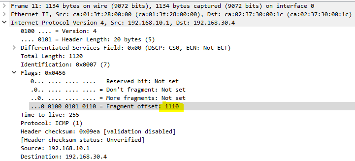
which turns out to be eight times the values of the fragment offset. So based on what I see here, it looks correct. To be honest, I don’t see the value of 688 as you see in packet number 11 below:
This is strange, because I did download your packet capture, and I do see that all of the rest of the values in your screenshot match mine as well. Another issue I see here is that your offset values are not actually divided by eight, and I believe that this has something to do with how your Wireshark decides to interpret and display information. It may be a version issue?
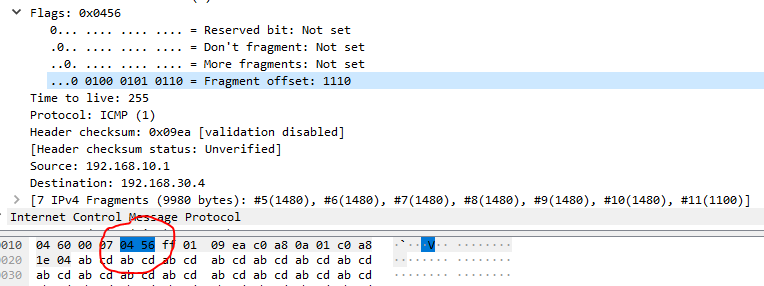
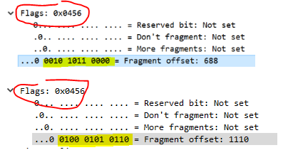
In the following screenshot, I’ve clicked on the fragment offset value, and the corresponding values are highlighted in the packet detail pane. Do you see the same values there?
04 56 in Hex is actually 1110 in decimal, which matches what I have in the pcap file. Take a look at yours as well and see what shows up with the value of 688. Also, confirm that you are looking at the correct pcap file, you may want to download it from your post above just to be sure that it’s not an incorrect file we’re looking at.
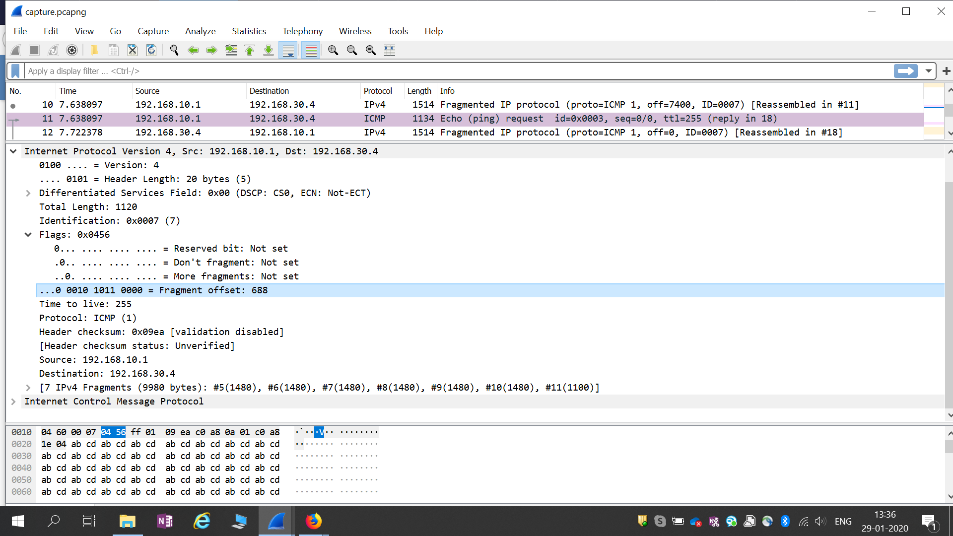
I have downloaded the same pcap file from this thread in another laptop and installed wireshark newly . And its showing 688 value for me and the hex value is as you have mentioned 04 56 which is same as i observed (I have selected the the offset field and the hex code is high lighted in screenshot) . May be some thing wrong . I not sure about it .
Thank you Laz .
i am attaching again my observation for the same frame .
Wireshark installed latest updated version .
That is indeed strange . The value 04 56 in hex is actually 1110 in decimal and not 688, so on a packet detail level, the information is correct. I also see that the binary value it shows in your output is 0010 1011 0000 which is indeed 688 while in mind it is 0100 0101 0110 which is 1110 in decimal.
Note that the value of the flags field, as indicated above is the same in both our outputs, but the offset values are different. To be honest, this shouldn’t be happening, and I’m not sure why it is happening.
As far as understanding the meaning of offset and of the fragmentation procedure, I believe you have understood it fully. If you’re interested in further pursuing this specific issue, you may want to open a new thread on the Wireshark forum, it may be interesting…
Is there any counters on the device that we can see dropped frame/packet/segment because of fragmentation?
I tested ping packets that larger than default 1500bytes value by setting DF flag. I saw the packets are bigger than 1500 bytes were dropped like exactly the same with your example, but I couldn’t find any counter to see how many packets dropped because of fragmentation issue
There are a couple of things involved in your question. If you are pinging a large packet (larger than 1500 bytes) and setting the DF bit to 1, then this will first of all affect the encapsulation of the host sending the ping. If you are doing this from a computer, then the PC will try to encapsulate the IP packet into a single frame without fragmenting it. If the MTU for the NIC card is at 1500, the encapsulation of the large IP packet into a single frame will fail. In this case, the packet/frame will never reach the switch port for a drop to register on any counter.
If the NIC is configured to send out larger frames, and the encapsulation is successful, then the frame will exit the NIC and reach the switchport. If the MTU of the frame is larger than the switchport supports, it will be dropped. Now note here that the counter that will increase on the interface in this case is the “giant” counter.
Note here that it is not possible for a switch to determine if a giant frame is giant because of a faulty fragmentation procedure, because this information exists in layer 3 and has been dealt with on another device, that is, the sending device. The switch will simply see that the size of the frame is larger than the allowed MTU, and will drop it, without regard to why it was larger. In order to determine this, you will have to troubleshoot at layer 3 and do so on the actual hosts sending the packets.
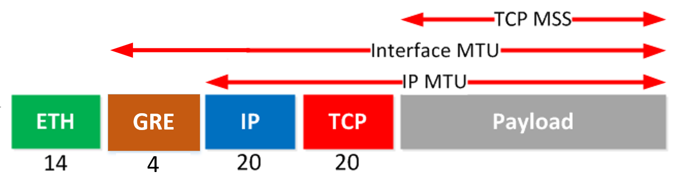
This is one of the confusing things about MTU. What we would like is to make sure that the maximum size of the payload of the frame will be 1500 bytes which is the Interface MTU. Now take a look at this slightly modified diagram:
The defining factor here is that we want the payload of the Ethernet frame not to surpass 1500.
The values of MTU are important at each stage of encapsulation. In order to achieve the goal of an Ethernet frame Payload of 1500 bytes or less, we must work our way backwards. Specifically:
Interface MTU = 1500
IP MTU = 1500 - 4 = 1496
TCP MSS = 1496 - 20 - 20 = 1456
Remember that by convention, the Interface MTU does not include the Ethernet header, the IP MTU includes the IP header, and the TCP MSS does not include the TCP header.
For this reason, the IP and TCP MSS MTUs must be smaller in order to accommodate the use of GRE.
Now it would be possible to simply increase the Interface MTU to make this work, however, the Interface MTU is not something that you always have control over. It will typically be on a third party network such as your ISP, so it’s not generally advisable to depend on this. And remember, the Interface MTU is something that exists on every interface of every link that the transmission traverses.
For this reason, it is always best to make the MTUs smaller on your end to ensure that they “fit” the unchangeable MTUs through which you will be transmitting your data.
I hope this has been helpful! Stay healthy and stay safe!
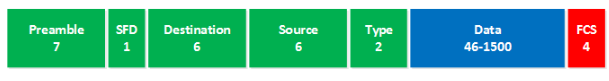
“This means that a single Ethernet frame can carry up to 1500 bytes of data. On top of this data we add the Ethernet header. Typical header sizes are 14 bytes for Ethernet (add another 4 bytes if you use 802.1Q tagging).”
In your diagram of an Ethernet header we had the field values:
– Preamble (7 - Bytes)
– SFD (1 - Bytes)
– Source (6 - Bytes)
– Destination (6 - Bytes)
– Type (2 - Bytes)
– SFC (4 - Bytes)
So, for example if i set mtu 1500 (layer 2) on routerA and mtu 1400 (layer 2) on routerB and then i ping from routerA to RouterB using size 1500 , then routerA will drop the pckts ? in L2 mtu both sides must exact match mtu size ?
What about if on RouterA i set ip mtu 1500 (layer 3) and on RouterB ip mtu 1400 (layer 3), then do the ping 1500 bytes from RouterA to RouterB, now RouterB can process this packet but fragmenting it on two smaller packets ? (1400 B + 100B)
preamble and SFD (Start of Frame Delimeter) doesn’t count , only the Destion, Source and Type fields (6+6+2) in the 802.3 Ethernet Frame, and then you could have a 802.1Q frame you have to add 4 extra Bytes for the vlan tag
Yes, I see your confusion. There are different ways that we measure the sizes of MTUs and headers, and what is included and what is not usually depends on the circumstances. When measuring the size of the frame header, we don’t take into account the preamble and SFD, but only the source, destination, and Type fields, which gives us 14 bytes. It’s a matter of convention. The preamble and SFD are used to separate frames, so they’re not technically part of the header, but are often mentioned and shown in diagrams such as the one you shared.
Similarly, when measuring MTU, you sometimes take into account the headers and others you don’t. For example, the IP MTU (layer 3) does take into account the IP header, and not just its payload. Conversely the Interface MTU (layer 2) doesn’t take the Ethernet header into account at all.
Remember that the MTU at layer 2 is implemented at the interface. So for your scenario, the interface of router A is configured with an MTU of 1500 and the interface of router B is configured with an MTU of 1400. If a 1500 byte frame is sent from A to B, then B will drop the frame, so yes you are correct. You don’t need an exact match on both ends, since smaller MTUs will go through, but for correct network functionality, the MTUs should match.
What you’re talking about here is the IP MTU. Unlike interface MTU, IP MTU is applied on an interface only in an outgoing direction. IP MTU determines the maximum size an IP packet that can be encapsualted into an Ethernet frame before being sent out an interface. So in your scenario, no fragmentation would take place. If you were to ping from B to A, then yes, there would be fragmentation. Remember, fragmentation can only take place outgoing (during encapsulation) and not incoming (during decapsulation).
Thank you so much. But why did you say on the IP MTU scenario , from B to A ? In my scenario A has 1500 B and B 1400 B , so 1400 < 1500 i dont undersand why fragmentation would be needed in this case
Remember that unlike the interface MTU, the IP MTU is only applied in an outgoing direction. It has no affect on incoming traffic. Therefore if you have router A with an IP MTU of 1500 and router B with an IP MTU of 1400, then any packet with an IP packet size of 1500 (including the header) going from A to B will successfully be sent by A, and received by B.
Conversely, if you have an IP packet of 1500 bytes that router B is preparing to send out of the interface to router A, during encapsulation, it will be fragmented before being sent due to the fact that the IP MTU is 1400.
I read through the whole forum chain to get a better understanding on the topic. A few things that I would need your help to clarify:
Let’s assume the IP MTU setup to 9000, If I setup interface MTU (L2 MTU) to 1500 while the DF set to 1, then the packets that’s larger than 1500 will be dropped. If I setup interface MTU to 1500 while the DF set to 0, then will the packets just be fragmented rather than dropped if it’s larger than 1500?
Will tcp adjust-mss value change automatically if I change the IP MTU value?
I don’t think I fully understand the word “payload” here. For a tcp packet, then the payload = the size of IP header + tcp header + data. If it’s a ICMP packet, then the payload = the size of ip header + ICMP header + data. Am I understand this correctly?
First of all, the IP MTU cannot be larger than the interface MTU. If you change the interface MTU value, the IP MTU value also changes simultaneously. When you change IP MTU value, the allowed values are up to and including the current interface MTU value:
R1(config-if)#ip mtu ?
  <68-1500>  MTU (bytes)

R1(config-if)#mtu 1400
R1(config-if)#ip mtu ?
  <68-1400>  MTU (bytes)

R1(config-if)#
Only the IP MTU is involved in the fragmentation of IP packets, and it only works in an outgoing direction. If an incoming packet is larger than the interface MTU, then it is simply dropped.
I tried to lab this up, and made changes to both the IP MTU and the interface MTU, but this had no affect on the adjust-mss value.
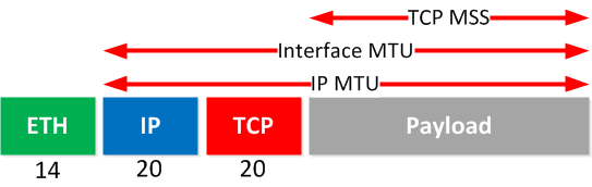
The payload of a TCP segment is simply the data. It does not include Ethernet, IP, or TCP headers. It only includes the contents of the segment, as shown in the image:
If you add the TCP header, the IP header and the Ethernet header to that value, you get the total size of the Ethernet frame which turns out to be 1514 bytes. The image above clearly distinguishes between each entity.
Remember that payload depends on the protocol in question. The payload of an IP packet is the sum of the TCP header and its payload. The payload of an Ethernet frame is the sum of the IP header, TCP header, and the TCP payload.
I understand that Jumbo frames are attractive to a customer as more as more data can be sent before an acknowledgement is required, resulting in a better performance.
My questions is why don’t ISPs always just support jumbo frames by default? Is there a negative impact on their network for allowing jumbo frames to pass?