This topic is to discuss the following lesson:
Good day!
This topic makes me go deeper to multicast! And i’ll explain why)
I could not understand why do we need 224.0.1.40 for R3 (permit rule in MULTICAST_FILTER acl). R3 is a client (receiver) of MC groups and all that we need for receiving multicast on R3 it is just sending IGMP report (join) toward the R2 (we can forget about PIM), and R2 knows where RP is.
Hours of labing I understood, the main reason why we need acl with 224.0.1.40 in MULTICAST_FILTER acl is “R3 acts as PIM-DR”
I think that we do not pass packets with dst ip 224.0.1.40 through R2 is not the main problem in this topology! (avoiding chicken-and-egg problem is important but …)
I Just think that the one of central points of this topic is PIM DR R3
my thoughts:
- IF Multicast client (receiver) was not the Cisco R3 (where PIM and IGMP coexist together), but just a real client PC (vlc player) then permit rule for 224.0.1.40 in MULTICAST_FILTER acl does not really needed
- IF R2 is PIM DR (ip pim dr-priority ..) then permit rule for 224.0.1.40 in MULTICAST_FILTER acl does not really needed
- if we use “ip pim passive” command on R3 then permit rule for 224.0.1.40 in MULTICAST_FILTER acl does not really needed
Just to make sure
Are my thoughts in the right way or I miss smth?
Ok, maybe a lot of letters…
Why do not we see the interface Gi0/2 of R2 in the OIL of the (*,G) entry in R2 when we use “ip igmp join-group” command for 239.1.1.1 and 239.2.2.2?
And why do we see it if R2 is PIM DR?
Hello Evgeny
I discussed this over with @ReneMolenaar and he said that the lesson may be somewhat confusing. Specifically, R3, as you correctly mentioned, plays the role of a multicast router as well as a multicast client. In the same way, R1 is a multicast source, and a multicast router. He said he would revise the content by adding a multicast source connected to R1 and a multicast client connected to R3 so these roles will be separate.
Now having said that, looking at your comments, we can say the following:
Yes, this is correct. If R3 was a host, the permit rule would not be needed. The permit rule is used so that R2 can find the DR which is R3.
This too is correct, since R2 is itself the DR it does not need the entry in the ACL to communicate with the DR.
The ip pim passive command will cause an interface to not send out or accept any PIM messages from other routers. The router will instead consider that it is the only PIM router on the network, and thus act as the DR. This command will actually cause PIM neighborships to not form, so the whole multicast topology will malfunction. @ReneMolenaar labbed it up and the topology did indeed fail. This command should only be used when there is only a single multicast router on the network. If there are more than one multicast routers, and you want to filter out PIM messages, use the ip pim neighbor-filter command instead. You can find out more about the passive functionality of PIM at the following Cisco command reference.
I hope this has been helpful!
Laz
Hello again Evgeny
After labbing this up with @ReneMolenaar we found that Gi0/2 did indeed appear in the OIL of the (*,G) entry in R2. You must keep in mind that it may take several minutes for the topology to reconverge so that this appears. Can you take a look at your configuration again and let us know if you get the same results?
I hope this has been helpful!
Laz
Good day!
I appreciate your attention!
Thanks a lot
About labbing..
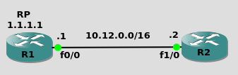
Just emulating that R1 is RP and that R2 doesn’t know RP address
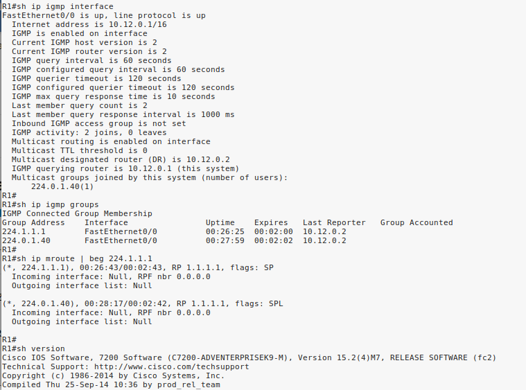
and after more than 10 min the situation in R1 is the same
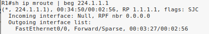
After input “ip pim passive” on Fa1/0 in R2, “shut/no shut” on Fa0/0 in R1 I can see iface Fa0/0 in the OIL
Hello Evgeny
This is expected behaviour. Remember that there is a difference between routing multicast traffic and processing multicast traffic. In order to process multicast traffic, all you need is a PIM command on the interface. It doesn’t matter if it is sparse mode, dense mode, or passive. In this topology that you have, there is no multicast routing, since we are looking only at a single network segment.
Take a look at the following example. For this, the 239.2.2.2 multicast group was used:
R1#debug ip multicast topology
R1#debug ip pim
R1#debug ip igmp
R1 doesn’t have anything in its OIL:
R1#show ip mroute 239.2.2.2

(*, 239.2.2.2), 00:03:05/00:02:55, RP 0.0.0.0, flags: SP
  Incoming interface: Null, RPF nbr 0.0.0.0
  Outgoing interface list: Null
R2 is the DR:
R1#show ip pim neighbor
PIM Neighbor Table
Mode: B - Bidir Capable, DR - Designated Router, N - Default DR Priority,
      P - Proxy Capable, S - State Refresh Capable, G - GenID Capable,
      L - DR Load-balancing Capable
Neighbor          Interface                Uptime/Expires    Ver   DR
Address                                                            Prio/Mode
10.12.0.2         GigabitEthernet0/1       00:04:17/00:01:23 v2    1 / DR S P G
Now let’s make R1 the DR:
R1(config-if)#ip pim dr-priority 2You see this output:
PIM(0): Changing DR for GigabitEthernet0/1, from 10.12.0.2 to 10.12.0.1 (this system)
%PIM-5-DRCHG: DR change from neighbor 10.12.0.2 to 10.12.0.1 on interface GigabitEthernet0/1
IGMP(0): MRT Add/Update GigabitEthernet0/1 for (*,224.0.1.40) by 3
MRT(0): Update (*,224.0.1.40), RPF (unknown, 0.0.0.0, 0/0)
MRT(0): Set the C-flag for (*, 224.0.1.40)
MRT(0): WAVL Insert interface: GigabitEthernet0/1 in (* ,224.0.1.40) Successful
MRT(0): set min mtu for (0.0.0.0, 224.0.1.40) 18010->1500
MRT(0): Add GigabitEthernet0/1/224.0.1.40 to the olist of (*, 224.0.1.40), Forward state - MAC built
IGMP(0): MRT Add/Update GigabitEthernet0/1 for (*,239.2.2.2) by 3
MRT(0): Update (*,239.2.2.2), RPF (unknown, 0.0.0.0, 0/0)
MRT(0): Set the C-flag for (*, 239.2.2.2)
MRT(0): WAVL Insert interface: GigabitEthernet0/1 in (* ,239.2.2.2) Successful
MRT(0): set min mtu for (0.0.0.0, 239.2.2.2) 18010->1500
MRT(0): Add GigabitEthernet0/1/239.2.2.2 to the olist of (*, 239.2.2.2), Forward state - MAC built
PIM(0): Building Triggered (*,G) Join / (S,G,RP-bit) Prune message for 239.2.2.2
R1 now becomes the DR, and the interface is added in the OIL.
Now the reason this same behaviour is seen when we use the passive command is because the PIM neighbor adjacency between R1 and R2 is severed, which means that R1 automatically becomes the DR, and this is the reason why the exit interface appears.
In both your example, as well as the example I described, the result is that R1 becomes the DR, albeit for different reasons. This is the reason for which the interface then appears.
It’s important to note that R1 still receives IGMP membership reports from R2, and so R1 receives them, processes them, and adds the interface to the OIL.
I hope this has been helpful!
Laz
Hi lagapides
what is the meaning of this command ?
R2(config-ext-nacl)#permit ip host 0.0.0.0 host 239.2.2.2
especially host 0.0.0.0
Hello Gowthamraj
Whenever the 0.0.0.0 address is used in this context, it has a special meaning. This meaning can be seen in RFC 5735. Specifically, for this address it states the following:
   0.0.0.0/8 - Addresses in this block refer to source hosts on "this"
   network.  Address 0.0.0.0/32 may be used as a source address for this
   host on this network; other addresses within 0.0.0.0/8 may be used to
   refer to specified hosts on this network.
Now in the case of the lesson, because the host keyword is being used, it is the 0.0.0.0/32 address that is specified. So in this case, this address is used as the source address for this host on this network.
So these particular entries allow multicast traffic destined to 239.1.1.1 and 239.2.2.2 that originate from the local device, namely R2.
I hope this has been helpful!
Laz
Hi Lagapides,
you mean using host 0.0.0.0 means it originated source from the local device. if its yes, then why we are using this here.
still i am not getting
Hello Gowthamraj
Your question got me thinking further, and after consulting with Rene and doing a bit more research, it seems that the host 0.0.0.0 when used in an ACL in conjunction with the ip multicast boundary command has a specific meaning. According to this Cisco Command Reference for this particular command:
Extended ACLs can also be used to define the (*, G) state to be permitted or denied on an interface, by specifying host 0.0.0.0 for the source address in the permit statements that compose the extended ACL.
So when used in this way, the host 0.0.0.0 refers to the (*,G) entries so that group information is filtered from autoRP messages.
Although my previous statement about host 0.0.0.0 is correct, it is interpreted differently when used in this way.
I hope this has been helpful!
Laz
Thank you as always.
I have a question.
After running the ip multicast boundary FILTER_AUTO_RP filter-autorp command on R2, running the show ip pim rp mapping command on R3 no longer displays anything. Why?
When I checked the Cisco site, I found the following:
An Auto-RP group range announcement is permitted and passed by the boundary only if all addresses in the Auto-RP group range are permitted by the boundary ACL. If any address is not permitted, the entire group range is filtered and removed from the Auto -RP message before the Auto-RP message is forwarded.
I added “224.0.1.40” to the allow list for the ACL “FILTER_AUTO_RP” and I got the expected results. Is this correct?
R2 (config) #ip access-list standard FILTER_AUTO_RP
R2 (config-std-nacl) #permit 224.0.1.40

R3 # sh ip pim rp mapping
PIM Group-to-RP Mappings

Group (s) 239.1.1.1/32
   RP 1.1.1.1 (?), V2 v1
     Info source: 1.1.1.1 (?), elected via Auto-RP
          Uptime: 00:01:32, expires: 00:01:25
Group (s) 239.2.2.2/32
   RP 1.1.1.1 (?), V2 v1
     Info source: 1.1.1.1 (?), elected via Auto-RP
          Uptime: 00:01:32, expires: 00:01:24
R3 #
Hello Yoichi
Well, it looks like you did some successful troubleshooting and research using Cisco documentation. You identified the problem, found an explanation in documentation, made the appropriate changes, and got the expected result to resolve your problem. I would have to say that that is a successfully executed troubleshooting process.
Now because Rene didn’t mention this in his lesson, I assumed that it was an issue with the behavior of a newer version of IOS, but I have done some research and confirmed that this behavior is the same for older versions of IOS.
I will let Rene know to take a look and see if he can add this detail to the information in the lesson.
I hope this has been helpful!
Laz
1 Like