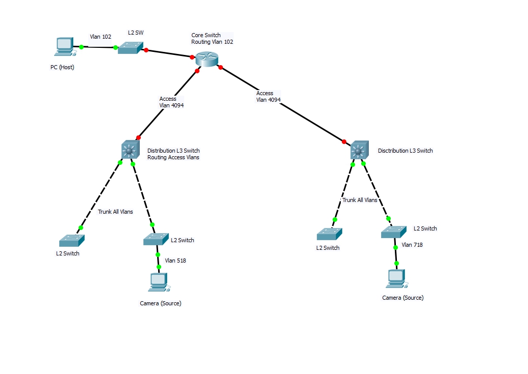
I have a network like below. My L3 distribution switch routing all access switch Vlans 518 and 718. My L3 and Core switch is connected with Access 4094. I have several video cameras in each L2 switch. My Host is connected with core switch vlan and source cameras are connected in L2 switch vlans. I have configured Manual RP in to the core switch and used PIM in Access mode 4094 to discover other L3 switch. I have configured PIM on source vlan 718 and 518 and host vlans 102. I have one multicast group 232.192.30.100 and all L3 switch have static RP address pointed. I have having issue getting multicast traffic from source. I have unicast traffic without any issue. When I ping multicast group, i got sometimes source camera valn gateway responding but not the multicast cameras. All cameras are configured with multicast ip address and camera is valid for multicast. Please need advice what I need to do in this situation.
Hi MD,
On each L3 device (router and L3 switches) you need to configure the static RP address, sounds like you did that. You also need to enable PIM on all L3 interfaces. You did that for VLAN 102, 518, 718 so that sounds correct.
IGMP snooping is enabled on your L2 switches?
When you send a ping from the source to 232.192.30.100. What do you see with show ip mroute? Which L3 devices forward your multicast traffic and which doesn’t?
Rene
Hi Rene,
Thanks for your reply.
----------- (Below my core switch config)----------
CoreSW#sh run int vlan 102
ip pim rp-address 10.130.11.1
interface Vlan102
 description Recipient-LAN
 ip address 10.130.0.1 255.255.255.0
 ip pim sparse-dense-mode
 ip igmp join-group 232.192.30.100
 ip igmp join-group 225.86.67.83
 ip policy route-map BLUETOAD-WWW
end
interface Vlan4094
 description Distribution Switch Trunk
 ip address 10.130.11.1 255.255.255.0
 ip pim sparse-dense-mode
 ip ospf priority 100
end
TerminatorX#sh ip pim neighbor
Neighbor          Interface                Uptime/Expires    Ver   DR
Address                                                            Prio/Mode
10.130.11.2       Vlan4094                 2d14h/00:01:24    v2    1 / S P G
10.130.11.4       Vlan4094                 2d10h/00:01:23    v2    1 / S P G
-------- (Below Distribution L3 switch config)-----------------
DelPrado_Vet_Pkwy-IE5000#sh run int vlan 4094
interface Vlan4094
 ip address 10.130.11.2 255.255.255.0
 ip pim sparse-dense-mode
end
DelPrado_Vet_Pkwy-IE5000#sh ip pim neighbor
PIM Neighbor Table
Neighbor          Interface                Uptime/Expires    Ver   DR
Address                                                            Prio/Mode
10.130.11.1       Vlan4094                 2d14h/00:01:39    v2    1 / S P G
10.130.11.4       Vlan4094                 2d10h/00:01:15    v2    1 / S P G

DelPrado_Vet_Pkwy-IE5000 (DistributionSW)#sh run int vlan 718
interface Vlan718
 ip address 10.129.160.193 255.255.255.240
 ip pim sparse-dense-mode
end

DelPrado_Vet_Pkwy-IE5000#sh ip igmp snooping vlan 718
Global IGMP Snooping configuration:
-------------------------------------------
IGMP snooping                : Enabled
IGMPv3 snooping (minimal)    : Enabled
Report suppression           : Enabled
TCN solicit query            : Disabled
TCN flood query count        : 2
Robustness variable          : 2
Last member query count      : 2
Last member query interval   : 1000

Vlan 718:
--------
IGMP snooping                       : Enabled
IGMPv2 immediate leave              : Disabled
Multicast router learning mode      : pim-dvmrp
CGMP interoperability mode          : IGMP_ONLY
Robustness variable                 : 2
Last member query count             : 2
Last member query interval          : 1000
DelPrado_Vet_Pkwy-IE5000#
DelPrado_Vet_Pkwy-IE5000#sh ip igmp groups (It does not show any group members for VLAN 718)
IGMP Connected Group Membership
Group Address    Interface                Uptime    Expires   Last Reporter   Group Accounted
239.255.255.250  Vlan778                  2d14h     00:02:51  10.129.168.194
239.255.255.250  Vlan768                  2d14h     00:02:58  10.129.167.195
239.255.255.250  Vlan728                  2d14h     00:02:16  10.129.161.195
225.86.67.83     Vlan778                  2d14h     00:02:54  10.129.168.194

DelPrado_Vet_Pkwy-IE5000#sh ip mroute 10.129.160.196 232.192.30.100
(*, 232.192.30.100), 00:05:17/stopped, RP 10.130.11.1, flags: SPF
  Incoming interface: Vlan4094, RPF nbr 10.130.11.1
  Outgoing interface list: Null

DelPrado_Vet_Pkwy-IE5000#ping 232.192.30.100
Reply to request 0 from 10.129.167.203, 24 ms
Reply to request 0 from 10.130.0.1, 35 ms
Reply to request 0 from 10.130.0.1, 35 ms
Reply to request 0 from 10.130.0.1, 35 ms
Reply to request 0 from 10.130.0.1, 31 ms
Reply to request 0 from 10.130.0.1, 31 ms
Reply to request 0 from 10.130.0.1, 31 ms
Reply to request 0 from 10.130.0.1, 31 ms
Reply to request 0 from 10.130.0.1, 24 ms
** I have 3 video cameras on this 718 VLAN and none of them are responding but i got Ping response from source 10.129.167.203 is not a member of 718 Vlan. I think the problem with multicast grouping. How can I add the source video cameras into the group 232.192.30.100?
Please advice. When I use show ip igmp membership i can see others groups are associated with the vlan but not the one I am requesting the group member 232.192.30.100
DelPrado_Vet_Pkwy-IE5000#sh ip igmp membership
 Channel/Group                  Reporter        Uptime   Exp.  Flags  Interface
 *,239.255.255.250              10.129.168.203  2d15h    02:19 2A     Vl778
 *,239.255.255.250              10.129.167.194  2d15h    02:26 2A     Vl768
 *,239.255.255.250              10.129.161.195  2d15h    02:22 2A     Vl728
 *,225.86.67.83                 10.129.168.194  2d15h    02:19 2A     Vl778
 *,225.86.67.83                 10.129.167.195  2d15h    02:25 2A     Vl768
 *,225.86.67.83                 10.129.161.195  2d15h    02:26 2A     Vl728
 *,224.0.1.39                   10.130.11.1     2d15h    02:46 2A     Vl4094
 *,224.0.1.40                   10.130.11.12    1d06h    02:58 2A     Vl4094


Colonial_6Mile-IE5000#sh ip igmp membership
 Channel/Group                  Reporter        Uptime   Exp.  Flags  Interface
 *,239.255.255.250              10.129.225.194  2d10h    02:04 2A     Vl528
 *,225.86.67.83                 10.129.225.194  2d10h    02:06 2A     Vl528
 *,224.0.1.39                   10.130.11.1     2d10h    02:46 2A     Vl4094
 *,224.0.1.40                   10.130.11.12    1d06h    02:44 2A     Vl4094
Let’s try to create a quick multicast troubleshooting checklist. I ran all show commands on this topology:
Some terminology I’ll use:
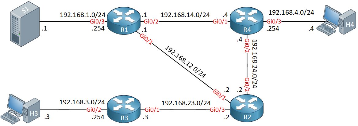
- First Hop Router (FHR): the router that is closest to the source.
- Last Hop Router (LHR): the router that is closest to the receiver(s).
Unicast Routing
First, make sure your unicast routing works. See if all your routers can reach the RP address:
R3#ping 2.2.2.2
Type escape sequence to abort.
Sending 5, 100-byte ICMP Echos to 2.2.2.2, timeout is 2 seconds:
!!!!!
Success rate is 100 percent (5/5), round-trip min/avg/max = 2/2/3 ms
Also, make sure you can ping the RP from the FHR’s interface that connects to your source:
R1#ping 2.2.2.2 source GigabitEthernet 0/1
Type escape sequence to abort.
Sending 5, 100-byte ICMP Echos to 2.2.2.2, timeout is 2 seconds:
Packet sent with a source address of 192.168.12.1
!!!!!
Success rate is 100 percent (5/5), round-trip min/avg/max = 2/2/3 ms
If you use SPT, make sure that the routers can reach your source:
R3#ping 192.168.1.1
Type escape sequence to abort.
Sending 5, 100-byte ICMP Echos to 192.168.1.1, timeout is 2 seconds:
!!!!!
Success rate is 100 percent (5/5), round-trip min/avg/max = 3/3/5 ms
A quick ping is enough unless you have ACLs in place.
L3 Multicast
First of all, is multicast routing enabled globally on all routers?
R3#show ip multicast | include Routing
  Multicast Routing: enabled
PIM neighbor adjacencies
Do you have PIM neighbor adjacencies between your routers?
R3#show ip pim neighbor
PIM Neighbor Table
Mode: B - Bidir Capable, DR - Designated Router, N - Default DR Priority,
      P - Proxy Capable, S - State Refresh Capable, G - GenID Capable,
      L - DR Load-balancing Capable
Neighbor          Interface                Uptime/Expires    Ver   DR
Address                                                            Prio/Mode
192.168.23.2      GigabitEthernet0/1       00:07:46/00:01:20 v2    1 / S P G
PIM enabled on interfaces that connect to source and receiver(s)
Is PIM enabled on interfaces of your FHR and LHR that connect to your source and receivers?
R1#show ip pim interface

Address          Interface                Ver/   Nbr    Query  DR         DR
                                          Mode   Count  Intvl  Prior
192.168.12.1     GigabitEthernet0/1       v2/S   1      30     1          192.168.12.2
192.168.14.1     GigabitEthernet0/2       v2/S   1      30     1          192.168.14.4
192.168.1.254    GigabitEthernet0/3       v2/S   0      30     1          192.168.1.254
RP address
If you use PIM sparse or sparse-dense mode, do all routers know who the RP is?
R3#show ip pim rp mapping
Auto-RP is not enabled
PIM Group-to-RP Mappings

Group(s): 224.0.0.0/4, Static
    RP: 2.2.2.2 (?)
IGMP snooping
Is IGMP snooping enabled on L2 switches in between your receiver(s) and the LHR?
show ip igmp snoopingIGMP joined groups
Do you see any joined groups on the LHR that connects to your receiver(s)?
R3#show ip igmp groups
IGMP Connected Group Membership
Group Address    Interface                Uptime    Expires   Last Reporter   Group Accounted
239.3.3.3        GigabitEthernet0/2       00:21:15  00:02:52  192.168.3.3
If you don’t have any receivers, you can simulate this from your LHR with the ip igmp join-group command on the interface that would connect to your receiver.
Multicast trace to RP
See if you can trace the RP from the routers:
R3#mtrace 2.2.2.2
Type escape sequence to abort.
Mtrace from 2.2.2.2 to 192.168.23.3 via RPF
From source (?) to destination (?)
Querying full reverse path...
 0  192.168.23.3
-1  192.168.23.3 ==> 192.168.23.3 PIM  [2.2.2.2/32]
When this checks out, you know this router can join the (*,G) for this RP.
Multicast trace for source
If you use SPT, let’s verify whether we can reach the source:
R3#mtrace 192.168.1.1
Type escape sequence to abort.
Mtrace from 192.168.1.1 to 192.168.23.3 via RPF
From source (?) to destination (?)
Querying full reverse path...
 0  192.168.23.3
-1  192.168.23.3 ==> 192.168.23.3 PIM  [192.168.1.0/24]
-2  192.168.23.2 ==> 192.168.12.2 PIM  [192.168.1.0/24]
-3  192.168.12.1 ==> 192.168.1.254 PIM_MT  [192.168.1.0/24]
-4  192.168.1.1
Now we know that when we switch to SPT, we can reach the source and RPF checks out.
Check mroute entries for (*,G)
Now check if we have an entry for our group towards the RP on all routers in between the receiver(s) and RP.
This is a router that connects to a receiver:
R3#show ip mroute 239.3.3.3

(*, 239.3.3.3), 00:40:48/00:02:17, RP 2.2.2.2, flags: SC
  Incoming interface: GigabitEthernet0/1, RPF nbr 192.168.23.2
  Outgoing interface list:
    GigabitEthernet0/2, Forward/Sparse, 00:40:48/00:02:17
This is the RP that connects to the router above:
R2#show ip mroute 239.3.3.3

(*, 239.3.3.3), 00:41:47/00:03:15, RP 2.2.2.2, flags: S
  Incoming interface: Null, RPF nbr 0.0.0.0
  Outgoing interface list:
    GigabitEthernet0/3, Forward/Sparse, 00:41:47/00:03:15
Verify that you see the correct incoming and outgoing interfaces.
Simulate traffic
Now let’s see whether we can send traffic from our source to the receiver(s). We’ll send a ping to the multicast group.
On the source:
S1#ping 239.3.3.3 repeat 10000Now verify whether the FHR that connects to your source receives the traffic:
R1#show ip mroute count | include Packets
Group: 239.3.3.3, Source count: 1, Packets forwarded: 722, Packets received: 722
The command above is a quick way to see whether it receives and forwards multicast packets.
R1#show ip mroute 239.3.3.3

(*, 239.3.3.3), 00:03:40/stopped, RP 2.2.2.2, flags: SPF
  Incoming interface: GigabitEthernet0/1, RPF nbr 192.168.12.2
  Outgoing interface list: Null

(192.168.1.1, 239.3.3.3), 00:03:40/00:02:11, flags: FT
  Incoming interface: GigabitEthernet0/3, RPF nbr 0.0.0.0
  Outgoing interface list:
    GigabitEthernet0/1, Forward/Sparse, 00:03:40/00:02:50
We need to look at the second entry above, our source is 192.168.1.1. This router is receiving it. Let’s check whether the RP receives this:
R2#show ip mroute 239.3.3.3

(*, 239.3.3.3), 00:49:15/00:02:38, RP 2.2.2.2, flags: S
  Incoming interface: Null, RPF nbr 0.0.0.0
  Outgoing interface list:
    GigabitEthernet0/3, Forward/Sparse, 00:49:15/00:02:38

(192.168.1.1, 239.3.3.3), 00:05:25/00:02:25, flags: T
  Incoming interface: GigabitEthernet0/1, RPF nbr 192.168.12.1
  Outgoing interface list:
    GigabitEthernet0/3, Forward/Sparse, 00:05:25/00:02:38
Above, we see the entry from our source as well. At least we now know that traffic makes it from the source to the RP.
Now you can check any of the other routers in between the RP and receiver(s):
R3#show ip mroute 239.3.3.3

(*, 239.3.3.3), 00:50:45/00:02:20, RP 2.2.2.2, flags: SC
  Incoming interface: GigabitEthernet0/1, RPF nbr 192.168.23.2
  Outgoing interface list:
    GigabitEthernet0/2, Forward/Sparse, 00:50:45/00:02:20
This router is below the RP so it uses the (*,G) entry.
Conclusion
With the steps above, you should be able to figure out where it goes wrong. If not, let us know on which step it fails and we’ll see if we can figure out what is wrong.
PS - you have these static igmp join-groups on your switch:
 ip igmp join-group 232.192.30.100
 ip igmp join-group 225.86.67.83
You don’t need those unless you were testing something.
Rene