Hello Laz.
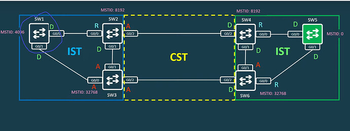
Okay, let’s get CML involved. The topology:
Before we connect these two regions together (they have different MST configuration), here is how the topology looks like:
SW3#show spanning-tree mst 0

MST0    vlans mapped:   51-4094
Bridge        address 5254.001e.a33a  priority      32768 (32768 sysid 0)
Root          address 5254.0005.3f4e  priority      4096  (4096 sysid 0)
              port    Gi0/0           path cost     0
Regional Root address 5254.0005.3f4e  priority      4096  (4096 sysid 0)
Notice how the root bridge and the regional root are the same. The RB here is SW1:
SW1#show spanning-tree mst 0

MST0    vlans mapped:   51-4094
Bridge        address 5254.0005.3f4e  priority      4096  (4096 sysid 0)
Root          this switch for the CIST
Since there is no CIST at the moment (the regions aren’t connected), SW1 is the RB for the blue region. Which makes sense because it has the lowest priority (4096). The RB for the IST and the regional RB will be the same in this case because again, we have just one region.
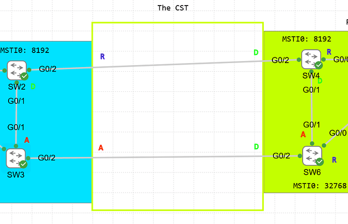
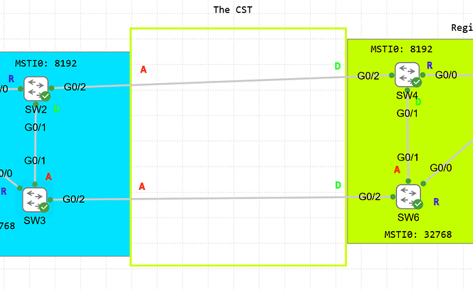
Now, let’s connect these regions together:
Now, we need to determine the port roles for the CST. We do this by electing a switch with the lowest BID from the connected regions as the CIST root bridge. This is SW5 because it has a priority of 0.
SW5#show spanning-tree mst 0

MST0    vlans mapped:   50-4094
Bridge        address 5254.0014.cba0  priority      0     (0 sysid 0)
Root          this switch for the CIST
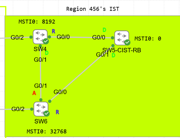
Let’s now calculate the port roles for the CST. The region with the RB has all ports as designated. We know that the CST sees the regions as two virtual bridges which means that it only concerns itself about what happens externally and not internally in the regions. In simple terms, the CST port roles are determined based off the lowest external path cost.
The link connecting the regions is a Gigabit link, so for both SW2 and SW3, the external pathcost will tie and be 20000. Since SW2 has a lower STP priority, it will have the root port for that segment.
And here goes the final step. If we kept the topology like this:
There would be a problem. SW2 has two root ports. This goes against the rules of STP. If we have more than one root port, we create the potential for a layer 2 loop to occcur.
So if we followed STP’s logic here, since it already has a root port and the region on the right is the designated bridge for that segment, that G0/2 port can only be alternate…
And now we have no communication between the regions.. So if my understanding is correct, MSTP changes the rules of its operation when connected to multiple regions.
First, it restarts the RB election and instead elects a regional root bridge. The regional root is the switch that is the closest to the neighboring region in terms of external path cost. The regional root for the blue region will be SW2 because it is the closest to the green region. SW2 and SW3 actually tie here, but SW2 wins because it has the lower STP priority.
SW2#show spanning-tree mst 0

MST0    vlans mapped:   51-4094
Bridge        address 5254.0014.330d  priority      8192  (8192 sysid 0)
Root          address 5254.0014.cba0  priority      0     (0 sysid 0)
              port    Gi0/2           path cost     20000
Regional Root this switch
Notice how SW2 is now the regional root bridge while SW5 is the CIST root bridge. SW1 is no longer the RB!
SW1#show spanning-tree mst 0

MST0    vlans mapped:   51-4094
Bridge        address 5254.0005.3f4e  priority      4096  (4096 sysid 0)
Root          address 5254.0014.cba0  priority      0     (0 sysid 0)
              port    Gi0/0           path cost     20000
Regional Root address 5254.0014.330d  priority      8192  (8192 sysid 0)
                                      internal cost 20000     rem hops 19
This follows what I’ve mentioned in my original diagram
If SW1 remained the RB, we would have problems.
However, if SW2 is elected as the regional RB
IT will provide an internal path for every switch in the blue region to reach the CIST root, thus to reach the green region. All switches in the blue region will calculate the port roles accordingly (to reach SW2 as quickly as possible).
This means that SW2’s non-boundary ports are designated. Since SW2 has no root ports now, it can actually elect G0/2 as one.
So SW2 becomes the regional root bridge while SW5 becomes the CIST root bridge. It’s a 2-tier hierarchy.
David


