Multiple Spanning Tree (MST)

Hi Rene,

In this situation the outside switch (SW4 in this example) will see IST0 Root switch of MST as its root switch, right? In the example also SW4 seeing SW1 as root switch for all of its vlans.
According to that I guess there is a mistake in this sentence of the article “Here’s VLAN 10, which is mapped to instance 1. SW4 sees SW2 as the root bridge for this VLAN even though we configured SW3 as the root bridge for instance 2.” Because SW4 is seeing same switch as Root switch for all of its VLANS and that is SW1 .

Hello Görgen

The output of the show spanning-tree vlan 10 command in the lesson that is found just above that statement is the following:

SW4#show spanning-tree vlan 10

VLAN0010
  Spanning tree enabled protocol ieee
  Root ID    Priority    4096
             Address     5254.0010.370d
             Cost        4
             Port        1 (GigabitEthernet0/0)
             Hello Time   2 sec  Max Age 20 sec  Forward Delay 15 sec

  Bridge ID  Priority    32778  (priority 32768 sys-id-ext 10)
             Address     5254.0017.2f95
             Hello Time   2 sec  Max Age 20 sec  Forward Delay 15 sec
             Aging Time  300 sec

Interface           Role Sts Cost      Prio.Nbr Type
------------------- ---- --- --------- -------- --------------------------------
Gi0/0               Root FWD 4         128.1    P2p 
Gi0/1               Altn BLK 4         128.2    P2p

Now you can see from this output that the ROOT bridge has a MAC address of 5254.0010.370d. Based on previous output, this is the MAC address of SW1. So the output is correct, but the statement, as you suggested is incorrect. It should say that:

…SW4 sees SW1 as the root bridge for this VLAN…

Thanks for catching that, I will let Rene know to make the adjustments.

Thanks again!

Laz

1 Like

Hi Laz,

It seems the changes are still not made which can cause confusion.
Also, I wanted to ask if my understand is correct…

What is the difference between PVST, PVST+ RPVST and RPVST+?
As per my understanding the actually STP versions are PVST+ and RPVST+ and not the ones without + sign. Also, PVST+ although runs STP instance per VLAN but it behaves like classic STP (802.1D) where timers are used to create a loop free topology and RPVST+ behaves like RSTP (802.1w) where “sync” mechanism is used to create a loop free topology while also having STP instance per VLAN.

Thanks!

Hello Rahul

I will let @ReneMolenaar know to make the changes.

PVST and RPVST are two Cisco proprietary protocols that were used for Cisco’s ISL, which is a proprietary trunk encapsulation protocol. ISL is no longer used in modern networks, and thus PVST and RPVST are also no longer used. Only the “+” versions are used, which support 802.1Q VLAN tagging. More info can be found at this NetworkLessons note.

Yes, this is correct.

I hope this has been helpful!

Laz

1 Like

Thanks for your confirmation. Appreciate it as always!

1 Like

Thank you, @andrew the Virtual Bridge ID concept is not clear for me, can you please explain in detail if possible

Hello Sathish

In the context of MST, the “Virtual Bridge” is a virtual entity that the MST region creates to interface with STP topologies that are outside of the MST domain. This virtual bridge is seen by the switches outside of the MST domain as a bridge with a specific bridge ID. So from the point of view of switches outside of the MST domain, they communicate and exchange BPDUs with that virtual bridge as if it is a single physical device.

The virtual bridge however is actually not a specific physical switch. It is actually a construct that is created within the MST domain using the process that Andrew described. The best bridge ID is determined from all the switches in instance 0 of the MST domain, and that bridge ID is shared with switches outside of the MST domain.

The result is that any switch outside of the MST domain that has a connection to one of the MST switches will see the whole MST domain as a single switch with the bridge ID that has been determined by MST as the best bridge ID in the domain. In this sense, switches outside of MST will perceive the whole MST domain as a single switch with the bridge ID that MST determines to be the best in its topology. Does that make sense?

I hope this has been helpful!

Laz

Hello, everyone.

I am at the start of the lesson since I’ve just started with MSTP so I started on viewing and reinforcing topics that I already know from the previous STP/RSTP versions by examining the MSTP BPDU.

However, the structure of it confuses me a little. I have this simple MSTP topology here:


There are a few things that don’t make much sense to me in the MSTP BPDU. Classic STP/RSTP include fields in their BPDUs that show the BID of the root bridge and the BID of the local switch. In MSTP, where exactly is this located? Is it correct to say that the “Regional Root Identifier” identifies who the root bridge is for each instance?


If so, where is the BID of the local switch, then? And why is the Proposal and Agreement bit set at the same time per instance? I can understand just one being set because that makes sense, but both?

David

Hello David

You’re on the right track. In MSTP, the “Regional Root Identifier” indeed identifies the root bridge for each instance. It is used to identify the root switch of the region for a specific instance. The bridge ID contains both the priority and the MAC address combined together - Bridge priority + MAC (System ID Extension + MAC in MSTP).

The Bridge Identifier of the local switch is located in the “CIST Bridge Identifier” field. You can see this as a field in the first screenshot you shared. The CIST (Common and Internal Spanning Tree) is the spanning tree that runs in an MST region that interconnects with other MST regions and with other types of spanning tree protocols.

As for the Proposal and Agreement bit being set at the same time, this may happen during the negotiation process of MSTP. The Proposal and Agreement flags are used to establish a rapid agreement on forwarding ports. When a switch sends a BPDU with the Proposal flag set, it is proposing to the downstream switch that it (the sender) should be the root port. The downstream switch, if it agrees, starts sending BPDUs with the Agreement flag set. This is how they communicate and agree on the state of the ports.

I hope this has been helpful!

Laz

Hello Laz.

I have a fairly large thing to discuss here, so I’ll split it into multiple posts as we progress on.

When it comes to MSTP, a region is defined by several parameters. I’ll mention one which are the instances and the VLANs mapped to them.

The moment we have different MSTP configuration, more regions end up being created. So if I have 10 switches and I define the following instances:

SW1-5
MSTI1 - VLANs 1-500
MSTI2 - VLANs 501-1000

SW6-10
MSTI1 - VLANs 1-20
MSTI2 - VLANs 21-30

This will create two regions, with each region having 5 switches that share the same configuration.

Now, to confirm, if these switches were in the same region, this could cause problems and complexity, right? I suppose it would be problematic if each instance was configured differently (had a different root bridge, port costs, etc) and then each switch would have to go ahead and compare those VLANs and apply the relevant configuration only to some instances, and not to mention that it would be inconsistent and harder to configure/maintain, and so on…

So is it right to say that to preserve clarity, configuration consistency, and ensure a loop-free topology, the switches are grouped into regions and potentially separated if their configuration differs?

David

Hello David

You’re absolutely correct. MST operates on the principle of grouping switches into regions based on their configuration. Each region acts as an independent entity. This simplifies the overall network topology and reduces the amount of BPDU information that needs to be exchanged between switches. It is important however that the switches within a particular region have a consistent configuration as far as the groupings of the VLANs go on a per instance basis.

In your example, SW1-5 forms one MST region and SW6-10 forms another MST region. Each region has its own instances with unique VLAN mappings. If these switches were in the same region with different configurations, it would not only cause complexity, but it will be non-functional. The mappings on each individual instance must be the same across all switches in the region. So yes, your understanding seems to be correct.

I hope this has been helpful!

Laz

Hello Laz.

Thank you. Here is where things get a little complicated.

If we connect different regions together, by default, they wouldn’t function correct if each region had different instances and VLAN mappings.

So the spanning-tree that actually runs between regions is the CST, correct? Whose function differs quite a lot. It turns out that the CST sees both regions as individual logical switches


And between these two virtual switches (I’ll call them that :smiley: ), you also need to determine the port roles, and such, correct?

So we need to determine the root bridge here from the perspective of the CST. For this reason, the switch with the lowest BID from all of the region’s ISTs becomes the root bridge. The union of all the ISTs and the CST is the CIST, so the CIST root bridge, right?

David

Hello David

Strictly speaking, the instances and VLAN mappings within each MST region do not need to be the same. What is configured within an MST region is considered a “black box” to any external STP topologies to which that region may interconnect, whether they are STP, RSTP, RPVST+ or MST. As you correctly stated, the MST region acts as one big switch from the point of view of any other STP topology, without concern with internal instances and mappings.

As you suggest, the CST sees each region as an individual logical switch and it’s the CST that runs between these regions. As for the port roles, you’re right again. They do need to be determined between these virtual switches.

As for the root bridge, it is indeed determined from the perspective of the CST. The switch with the lowest Bridge ID from all of the region’s ISTs becomes the root bridge. This root bridge is known as the Common and Internal Spanning Tree (CIST) root bridge.

The CIST is essentially a superset of all the ISTs and the CST, and it’s responsible for ensuring that there is a loop-free topology across all the regions.

Does that clear things up? Let me know if you have further questions!

I hope this has been helpful!

Laz

Hello Laz.

Yes, that’s perfect. Here comes the final thing:

Why does every region have a regional root bridge? The moment you connect different regions together, you expand your IST domain and create a single union of the ISTs + the CST = CIST.

This causes the devices outside of the CIST root bridge’s region to actually change their IST topology?

To provide some more clarity, consider this topology

These are two different regions that are not yet connected. Both have their own IST topology and also the relevant MSTP topologies for MSTI1 and MSTI2.

Notice how SW1 and SW5 are the RBs (root bridges). If we then connect these two regions together:

SW5 becomes the CIST RB and SW2 becomes the regional RB for the blue region.

The question I initially had was “why?”, why couldn’t SW1 remain the root for the blue region? Why are there these regional root bridges in the first place?

But after thinking about it, we need regional roots because they determine path selection inside of the region. Because consider this, if SW1 did remain the root:


//edit: Made a mistake, SW3’s G0/0 port was supposed to be the root in my diagram above, sorry

SW2 would elect G0/0 as its root port. Since it already has a root port and SW4 is the designated bridge for the CST segment, it would just pick the G0/2 port to be alternate, and so would SW3, right? So this means that no communication would be possible between the regions. Is this correct?

However, if SW2 is the regional root bridge, everyone inside the blue region will point their port roles towards it which will allow them to eventually reach the CIST root., because:

SW2’s non-boundary ports are designated
SW2’s boundary port is a root port that can reach the CIST root

Thanks for the discussion. MSTP sure gets complex when you consider it like this. Single-region designs and topics are quite simple but the moment you connect more of them together, CST gets involved, CIST gets involved, external path cost gets involved, each region has a regional RB while the entire CIST also has a CIST RB, it gets a little complicated.

David

Hello David

Hmm, that’s an interesting scenario. You are correct in your statement:

However, when you connect two MST regions and a CIST root bridge is chosen, this connection should not change the regional root bridges you have within each MST region for your internal MST instances. You must keep in mind that the port roles for the internal MST region are not the same as the port roles in the CST. Regardless of whether SW1 or SW2 is the root bridge for the internal blue MST region, because SW5 is the CIST root, one of the two Gi0/2 ports on SW2 or SW3 will become a root port for the CST. The roles you have in your final diagram are those of the blue IST, with SW1 as the root.

Now my question here is, how did you determine that SW2 became the regional RB after the two regions were connected? Did this actually change once you connected them? By definition, the election of the CIST root does not directly affect the regional root bridges within each MST region. The regional root bridges remain as they are, determined by the MST protocol within their respective regions. The CIST root bridge provides an external reference for inter-region communication only, and does not alter the internal MST instance topology.

Can you share with us more info about that root bridge change in the blue IST and how and when it takes place?

I hope this has been helpful!

Laz

Hello Laz.

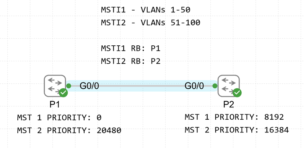
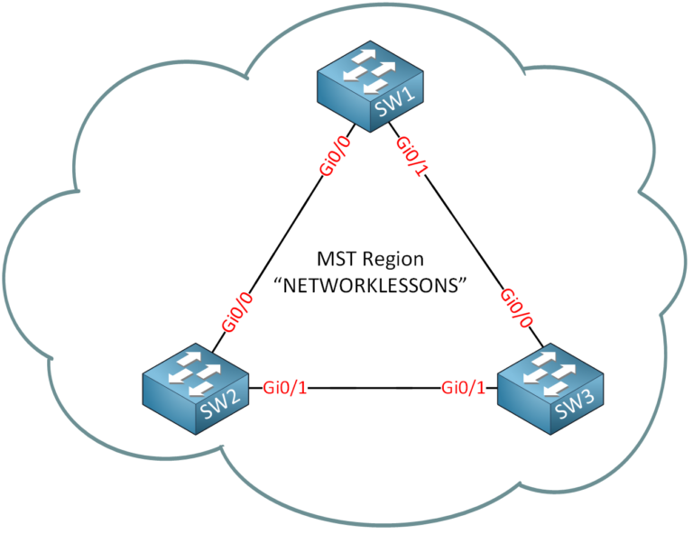
Okay, let’s get CML involved. The topology:

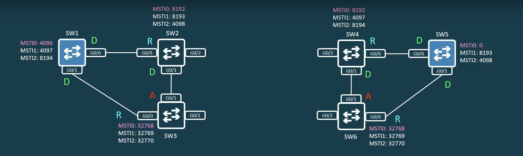
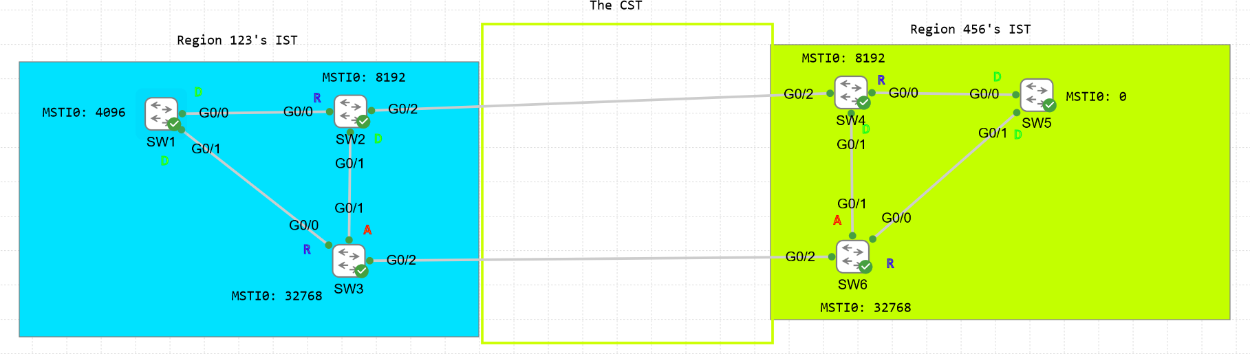
Before we connect these two regions together (they have different MST configuration), here is how the topology looks like:

SW3#show spanning-tree mst 0

MST0    vlans mapped:   51-4094
Bridge        address 5254.001e.a33a  priority      32768 (32768 sysid 0)
Root          address 5254.0005.3f4e  priority      4096  (4096 sysid 0)
              port    Gi0/0           path cost     0        
Regional Root address 5254.0005.3f4e  priority      4096  (4096 sysid 0)

Notice how the root bridge and the regional root are the same. The RB here is SW1:

SW1#show spanning-tree mst 0

MST0    vlans mapped:   51-4094
Bridge        address 5254.0005.3f4e  priority      4096  (4096 sysid 0)
Root          this switch for the CIST

Since there is no CIST at the moment (the regions aren’t connected), SW1 is the RB for the blue region. Which makes sense because it has the lowest priority (4096). The RB for the IST and the regional RB will be the same in this case because again, we have just one region.

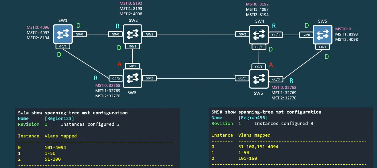
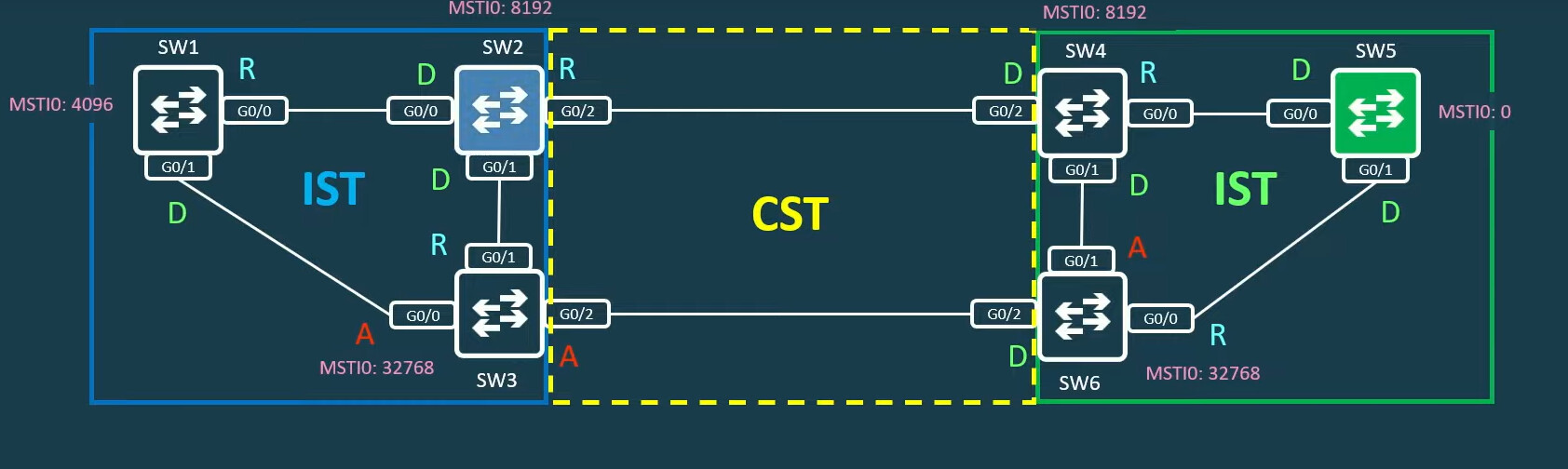
Now, let’s connect these regions together:

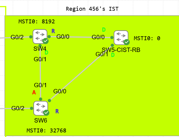
Now, we need to determine the port roles for the CST. We do this by electing a switch with the lowest BID from the connected regions as the CIST root bridge. This is SW5 because it has a priority of 0.
obrázok

SW5#show spanning-tree mst 0

MST0    vlans mapped:   50-4094
Bridge        address 5254.0014.cba0  priority      0     (0 sysid 0)
Root          this switch for the CIST

Let’s now calculate the port roles for the CST. The region with the RB has all ports as designated. We know that the CST sees the regions as two virtual bridges which means that it only concerns itself about what happens externally and not internally in the regions. In simple terms, the CST port roles are determined based off the lowest external path cost.

The link connecting the regions is a Gigabit link, so for both SW2 and SW3, the external pathcost will tie and be 20000. Since SW2 has a lower STP priority, it will have the root port for that segment.

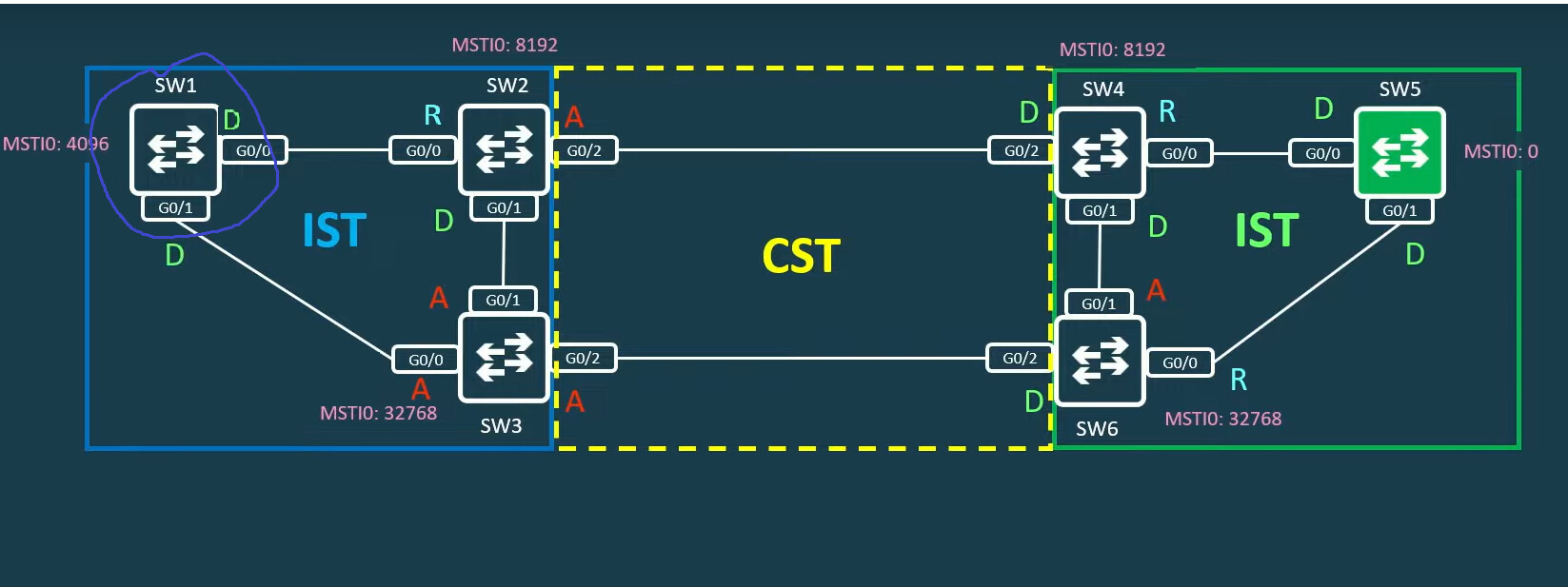
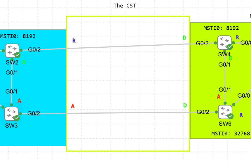
And here goes the final step. If we kept the topology like this:

There would be a problem. SW2 has two root ports. This goes against the rules of STP. If we have more than one root port, we create the potential for a layer 2 loop to occcur.

So if we followed STP’s logic here, since it already has a root port and the region on the right is the designated bridge for that segment, that G0/2 port can only be alternate…

And now we have no communication between the regions… So if my understanding is correct, MSTP changes the rules of its operation when connected to multiple regions.

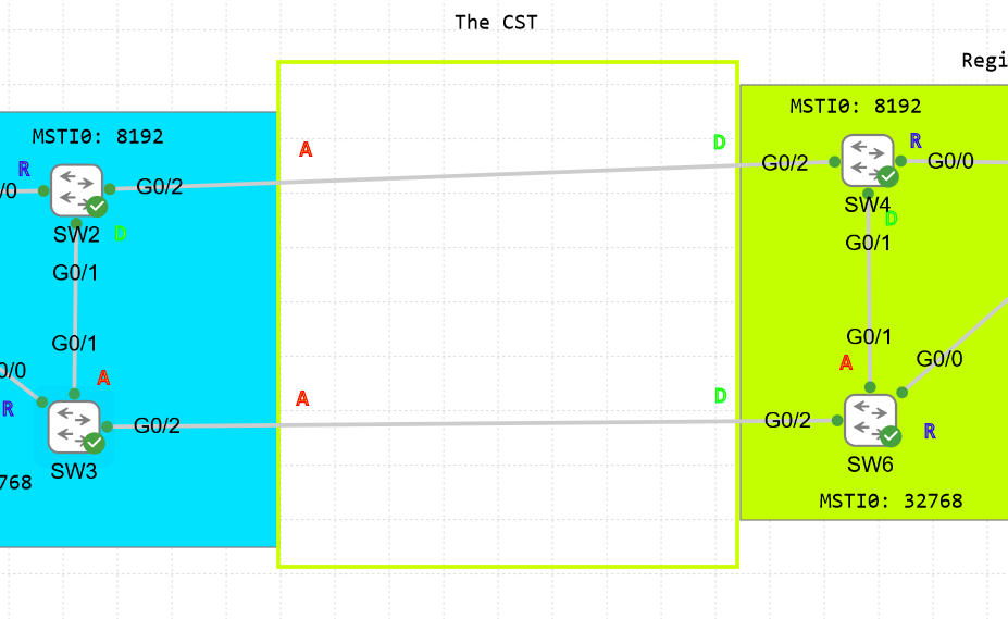
First, it restarts the RB election and instead elects a regional root bridge. The regional root is the switch that is the closest to the neighboring region in terms of external path cost. The regional root for the blue region will be SW2 because it is the closest to the green region. SW2 and SW3 actually tie here, but SW2 wins because it has the lower STP priority.

SW2#show spanning-tree mst 0

MST0    vlans mapped:   51-4094
Bridge        address 5254.0014.330d  priority      8192  (8192 sysid 0)
Root          address 5254.0014.cba0  priority      0     (0 sysid 0)
              port    Gi0/2           path cost     20000    
Regional Root this switch

Notice how SW2 is now the regional root bridge while SW5 is the CIST root bridge. SW1 is no longer the RB!

SW1#show spanning-tree mst 0

MST0    vlans mapped:   51-4094
Bridge        address 5254.0005.3f4e  priority      4096  (4096 sysid 0)
Root          address 5254.0014.cba0  priority      0     (0 sysid 0)
              port    Gi0/0           path cost     20000    
Regional Root address 5254.0014.330d  priority      8192  (8192 sysid 0)
                                      internal cost 20000     rem hops 19

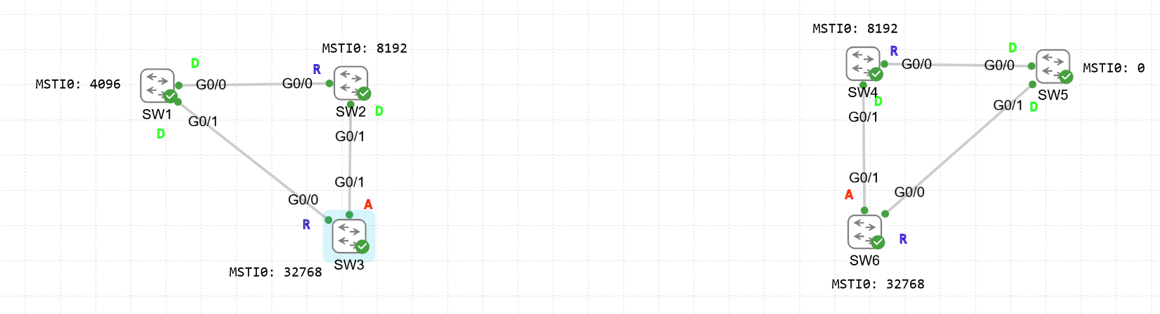
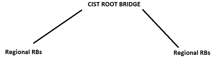
This follows what I’ve mentioned in my original diagram


If SW1 remained the RB, we would have problems.

However, if SW2 is elected as the regional RB


IT will provide an internal path for every switch in the blue region to reach the CIST root, thus to reach the green region. All switches in the blue region will calculate the port roles accordingly (to reach SW2 as quickly as possible).

This means that SW2’s non-boundary ports are designated. Since SW2 has no root ports now, it can actually elect G0/2 as one.

So SW2 becomes the regional root bridge while SW5 becomes the CIST root bridge. It’s a 2-tier hierarchy.

David

Hello David

Your explanations and your process are excellent, thank you for sharing in such detail.

I stand corrected in my assumption in my previous post. The rule that is stated in Cisco documentation is the following:

If the CIST root is outside the region, the protocol selects one of the MST switches at the boundary of the region as the CIST regional root.

So in your case, when you connected the two regions, since the CIST root (SW5) was outside of the blue region’s IST, the blue region had to recalculate its own regional root bridge to be on the boundary, which is why SW2 was chosen.

Now how is the correct new regional root chosen? You are correct in your statement:

Actually, to refine your statement just a bit, the IEEE 802.1Q-2005 states specifically that:

…within each MST region, the IST root should be the switch with the lowest path cost to the CST root. This ensures that traffic within the region takes the most efficient path to the CST root, minimizing the overall network path cost.

Thanks so much for your thoroughness and clarity!

I hope this has been helpful!

Laz