Andrew,
(P.S anyone reading this might want to read from bottom up I figured it out but don’t know for sure why it works the way it does)
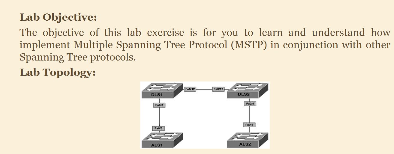
I was going through Cisco CCNP Switch Simplified and a lab lesson did not work for me. Its the very second lab at the end of the book
Basically they setup MST on DLS1 and DLS2 and then have change configuration on IST 0 so that its the root and they use that as a tool to explain how you have to understand how the IST works because changing priority on the others would not be seen by the switches outside the of the internal MST.
they basically have vlan 100 on ALS1 with SVI for the 192.168.100.0 255.255.255.0 network and setup a default-gateway pointing to DLS1 which has SVI for both VLAN 100 and VLAN 200 and SVI for each, (note DLS2 is setup the same way and ALS2 is setup like ALS1 except for VLAN 200 and has SVI for 192.168.200.0 255.255.255.0 network)
anyway they have you setup ip routing on both the distribution switches.
then they want you to ping from VLAN 100 on ALS1 switch to ALS2 switch which is VLAN 200.
So ping from 192.168.100.254 to 192.168.200.254 I have my configuration setup perfectly like they asked but I cannot ping.
I am using CISCO VIRL.
now here is the funny thing. I set this up in Boson Simulator which runs different IOS(edited: Boson has older switches that had to have layer three turned on to work not automatic like CISCO VIRL) version it works. I can ping. I set this up in Cisco VIRL it does not work.
below is cisco VIRL configs:
version 15.2
service timestamps debug datetime msec
service timestamps log datetime msec
no service password-encryption
service compress-config
!
hostname DLS1
!
boot-start-marker
boot-end-marker
!
!
!
no aaa new-model
!
!
!
!
!
vtp domain HARD
vtp mode transparent
!
!
!
ip cef
no ipv6 cef
!
!
!
spanning-tree mode mst
spanning-tree extend system-id
!
spanning-tree mst configuration
name DLS1-REGION
instance 1 vlan 100, 200
!
spanning-tree mst 0 priority 0
!
vlan internal allocation policy ascending
!
vlan 100,200
!
!
!
!
interface GigabitEthernet0/0
media-type rj45
negotiation auto
!
interface GigabitEthernet0/1
switchport trunk encapsulation dot1q
switchport mode trunk
media-type rj45
negotiation auto
!
interface GigabitEthernet0/2
switchport trunk encapsulation dot1q
switchport mode trunk
media-type rj45
negotiation auto
!
interface Vlan100
ip address 192.168.100.1 255.255.255.0
!
interface Vlan200
ip address 192.168.200.1 255.255.255.0
!
ip forward-protocol nd
!
no ip http server
no ip http secure-server
!
!
!
control-plane
!
banner exec ^C
.
.
.
.
.
.
version 15.2
service timestamps debug datetime msec
service timestamps log datetime msec
no service password-encryption
service compress-config
!
hostname DLS2
!
boot-start-marker
boot-end-marker
!
!
!
no aaa new-model
!
!
!
!
!
vtp domain HARD
vtp mode transparent
!
!
!
ip cef
no ipv6 cef
!
!
!
spanning-tree mode mst
spanning-tree extend system-id
!
spanning-tree mst configuration
name DLS2-REGION
revision 5
instance 3 vlan 100, 200
!
!
vlan internal allocation policy ascending
!
vlan 100,200
!
!
interface GigabitEthernet0/0
media-type rj45
negotiation auto
!
interface GigabitEthernet0/1
switchport trunk encapsulation dot1q
switchport mode trunk
media-type rj45
negotiation auto
!
interface GigabitEthernet0/2
switchport trunk encapsulation dot1q
switchport mode trunk
media-type rj45
negotiation auto
!
interface Vlan100
ip address 192.168.100.2 255.255.255.0
!
interface Vlan200
ip address 192.168.200.2 255.255.255.0
!
ip forward-protocol nd
!
no ip http server
no ip http secure-server
!
!
!
!
!
!
control-plane
!
banner exec ^C
.
.
.
.
.
.
version 15.2
service timestamps debug datetime msec
service timestamps log datetime msec
no service password-encryption
service compress-config
!
hostname ALS1
!
boot-start-marker
boot-end-marker
!
!
!
no aaa new-model
!
!
!
!
!
vtp domain HARD
vtp mode transparent
!
!
!
ip cef
no ipv6 cef
!
!
!
spanning-tree mode rapid-pvst
spanning-tree extend system-id
!
vlan internal allocation policy ascending
!
vlan 100
!
!
!
!
interface GigabitEthernet0/0
media-type rj45
negotiation auto
!
interface GigabitEthernet0/1
switchport trunk encapsulation dot1q
switchport mode trunk
media-type rj45
negotiation auto
!
interface Vlan100
ip address 192.168.100.254 255.255.255.0
!
ip default-gateway 192.168.100.1
ip forward-protocol nd
!
no ip http server
no ip http secure-server
!
!
!
!
!
!
control-plane
!
banner exec ^C
.
.
.
.
.
.
version 15.2
service timestamps debug datetime msec
service timestamps log datetime msec
no service password-encryption
service compress-config
!
hostname ALS2
!
boot-start-marker
boot-end-marker
!
!
!
no aaa new-model
!
!
!
!
!
!
!
!
ip cef
no ipv6 cef
!
!
!
spanning-tree mode rapid-pvst
spanning-tree extend system-id
!
vlan internal allocation policy ascending
!
!
interface GigabitEthernet0/0
media-type rj45
negotiation auto
!
interface GigabitEthernet0/1
media-type rj45
negotiation auto
!
interface Vlan200
ip address 192.168.200.254 255.255.255.0
!
ip default-gateway 192.168.200.2
ip forward-protocol nd
!
no ip http server
no ip http secure-server
!
!
!
!
!
!
control-plane
!
banner exec ^C
I redid the labs over a couple times and each time CISCO VIRL will not allow me to ping and I figured maybe something to do with arp table or the different version???
Boson is programmed but boson is good about working on basic stuff and simple commands for each of ccnp topics which makes me think its something going on with cisco VIRL
boson:
I was going to add the Boson configs but I cannot figure out how to copy and paste them lol… does not seem to be an option for that.
I will say they are the exact same minus uses fast Ethernet ports instead of gigabit. also uses version 15.b if that means anything.
I will post some other misc stuff below from CISCO VIRL just in case:
DLS1#show ip int br
Interface IP-Address OK? Method Status Protocol
GigabitEthernet0/0 unassigned YES unset up up
GigabitEthernet0/1 unassigned YES unset up up
GigabitEthernet0/2 unassigned YES unset up up
Vlan100 192.168.100.1 YES manual up up
Vlan200 192.168.200.1 YES manual up up
DLS1#show vlan brief
VLAN Name Status Ports
1 default active Gi0/0
100 VLAN0100 active
200 VLAN0200 active
1002 fddi-default act/unsup
1003 token-ring-default act/unsup
1004 fddinet-default act/unsup
1005 trnet-default act/unsup
DLS1#show int trunk
Port Mode Encapsulation Status Native vlan
Gi0/1 on 802.1q trunking 1
Gi0/2 on 802.1q trunking 1
Port Vlans allowed on trunk
Gi0/1 1-4094
Gi0/2 1-4094
Port Vlans allowed and active in management domain
Gi0/1 1,100,200
Gi0/2 1,100,200
Port Vlans in spanning tree forwarding state and not pruned
Gi0/1 1,100,200
Gi0/2 1,100,200
DLS1#
.
..
DLS2#show ip int br
Interface IP-Address OK? Method Status Protocol
GigabitEthernet0/0 unassigned YES unset up up
GigabitEthernet0/1 unassigned YES unset up up
GigabitEthernet0/2 unassigned YES unset up up
Vlan100 192.168.100.2 YES manual up up
Vlan200 192.168.200.2 YES manual up up
DLS2#show vlan brief
VLAN Name Status Ports
1 default active Gi0/0
100 VLAN0100 active
200 VLAN0200 active
1002 fddi-default act/unsup
1003 token-ring-default act/unsup
1004 fddinet-default act/unsup
1005 trnet-default act/unsup
DLS2#show int trunk
Port Mode Encapsulation Status Native vlan
Gi0/1 on 802.1q trunking 1
Gi0/2 on 802.1q trunking 1
Port Vlans allowed on trunk
Gi0/1 1-4094
Gi0/2 1-4094
Port Vlans allowed and active in management domain
Gi0/1 1,100,200
Gi0/2 1,100,200
Port Vlans in spanning tree forwarding state and not pruned
Gi0/1 1,100,200
Gi0/2 1,100,200
DLS2#
.
..
ALS1#show ip int br
Interface IP-Address OK? Method Status Protocol
GigabitEthernet0/0 unassigned YES unset up up
GigabitEthernet0/1 unassigned YES unset up up
Vlan100 192.168.100.254 YES manual up up
ALS1#show vlan bri
VLAN Name Status Ports
1 default active Gi0/0
100 VLAN0100 active
1002 fddi-default act/unsup
1003 token-ring-default act/unsup
1004 fddinet-default act/unsup
1005 trnet-default act/unsup
ALS1#show int trunk
Port Mode Encapsulation Status Native vlan
Gi0/1 on 802.1q trunking 1
Port Vlans allowed on trunk
Gi0/1 1-4094
Port Vlans allowed and active in management domain
Gi0/1 1,100
Port Vlans in spanning tree forwarding state and not pruned
Gi0/1 1,100
ALS1#
.
..
ALS2#show ip int br
Interface IP-Address OK? Method Status Protocol
GigabitEthernet0/0 unassigned YES unset up up
GigabitEthernet0/1 unassigned YES unset up up
Vlan200 192.168.200.254 YES manual up up
ALS2#show vlan brief
VLAN Name Status Ports
1 default active Gi0/0
200 VLAN0200 active
1002 fddi-default act/unsup
1003 token-ring-default act/unsup
1004 fddinet-default act/unsup
1005 trnet-default act/unsup
ALS2#show int trunk
Port Mode Encapsulation Status Native vlan
Gi0/1 auto n-802.1q trunking 1
Port Vlans allowed on trunk
Gi0/1 1-4094
Port Vlans allowed and active in management domain
Gi0/1 1,200
Port Vlans in spanning tree forwarding state and not pruned
Gi0/1 1,200
ALS2#
.
..
ALS1#ping 192.168.100.1
Type escape sequence to abort.
Sending 5, 100-byte ICMP Echos to 192.168.100.1, timeout is 2 seconds:
.!!!
Success rate is 80 percent (4/5), round-trip min/avg/max = 4/5/7 ms
ALS1#ping 192.168.200.1
Type escape sequence to abort.
Sending 5, 100-byte ICMP Echos to 192.168.200.1, timeout is 2 seconds:
…
Success rate is 0 percent (0/5)
ALS1#
.
..
DLS1#ping 192.168.100.254 source 192.168.200.1
Type escape sequence to abort.
Sending 5, 100-byte ICMP Echos to 192.168.100.254, timeout is 2 seconds:
Packet sent with a source address of 192.168.200.1
…
Success rate is 0 percent (0/5)
DLS1#ping 192.168.100.254 so
DLS1#ping 192.168.100.254 source 192.168.100.1
Type escape sequence to abort.
Sending 5, 100-byte ICMP Echos to 192.168.100.254, timeout is 2 seconds:
Packet sent with a source address of 192.168.100.1
!!!
Success rate is 100 percent (5/5), round-trip min/avg/max = 4/5/10 ms
DLS1#
.
..
DLS2#ping 192.168.100.254 source 192.168.100.2
Type escape sequence to abort.
Sending 5, 100-byte ICMP Echos to 192.168.100.254, timeout is 2 seconds:
Packet sent with a source address of 192.168.100.2
!!!
Success rate is 100 percent (5/5), round-trip min/avg/max = 6/6/7 ms
DLS2#ping 192.168.100.254 source 192.168.200.2
Type escape sequence to abort.
Sending 5, 100-byte ICMP Echos to 192.168.100.254, timeout is 2 seconds:
Packet sent with a source address of 192.168.200.2
…
Success rate is 0 percent (0/5)
DLS2#
.
..
I think I will cry if SVI are not working correctly on CISCO VIRL as that is a primary ability of switching. if an SVI is setup and routing enabled it should be able to access data from both VLAN 100 and VLAN 200.
I know sometimes the problem is a return route meaning it can get somewhere but does not know its way back
but that should not be the case here in my thinking… for example:
- I ping DLS1 from ALS1
- ALS1 does not know this 192.168.200.1 address so what does it do?
- it sends the address to its default-gateway to figure out.
- Once the packet is pushed over to DLS1 the switch sees that IP belongs to itself.
- Also even on top of that it has the routes in its routing table!!!
Gateway of last resort is not set
192.168.100.0/24 is variably subnetted, 2 subnets, 2 masks
C 192.168.100.0/24 is directly connected, Vlan100
L 192.168.100.1/32 is directly connected, Vlan100
192.168.200.0/24 is variably subnetted, 2 subnets, 2 masks
C 192.168.200.0/24 is directly connected, Vlan200
L 192.168.200.1/32 is directly connected, Vlan200
DLS1#
am I missing something here?
Also that Boson works re-affirmed that thinking but I just want to figure out if this is truly glitch with Cisco VIRL or if I am having a stupid moment or missing something that has to do with new switch model.
Cisco VIRL switches do about everything even this access is still layer three and had routing table see below:
ALS1#show ip route
Codes: L - local, C - connected, S - static, R - RIP, M - mobile, B - BGP
D - EIGRP, EX - EIGRP external, O - OSPF, IA - OSPF inter area
N1 - OSPF NSSA external type 1, N2 - OSPF NSSA external type 2
E1 - OSPF external type 1, E2 - OSPF external type 2
i - IS-IS, su - IS-IS summary, L1 - IS-IS level-1, L2 - IS-IS level-2
ia - IS-IS inter area, * - candidate default, U - per-user static route
o - ODR, P - periodic downloaded static route, H - NHRP, l - LISP
a - application route
+ - replicated route, % - next hop override
Gateway of last resort is not set
192.168.100.0/24 is variably subnetted, 2 subnets, 2 masks
C 192.168.100.0/24 is directly connected, Vlan100
L 192.168.100.254/32 is directly connected, Vlan100
ALS1#
..
..
OMG that was it… I just figured it out by accident. I thought what the heck why not just for the hex of it turn off IP Routing on the access switch.. I was thinking even though I didn’t know why that perhaps it having a routing table was making it not send off packet to DG or something crazy…
see below:
ALS1(config)#no ip routing
ALS1(config)#end
ALS1#ping 192.168.200.1
Type escape sequence to abort.
Sending 5, 100-byte ICMP Echos to 192.168.200.1, timeout is 2 seconds:
!!!
Success rate is 100 percent (5/5), round-trip min/avg/max = 4/205/1007 ms
ALS1#
..
.
Can someone explain why? I can guess at it and say because they are acting like routers just like a router we need routes for everything either static or dynamic such as OSPF, or EIGRP. However, I am guessing and I don’t really know as I am just trying to find some rationale logic to make sense of this crap!!!
edited: I did find the following link and while its not super granular it seems to confirm the reason:
some cisco specific stuff:
http://www.cisco.com/c/en/us/support/docs/lan-switching/inter-vlan-routing/41860-howto-L3-intervlanrouting.html
and this one:
ah my world is all happy again till the next time!!! =)
I am big time CISCO VIRL user so l will make tip to turn off IP routing on the switches as that’s the default on the switches.