Is a MUST in a Service Provider enviroment where run have thousands of vlans configured and in production. I Work for an ISP and we have MST , the difference is the Root Bridges we use runs IOS XR (ASR9K) and its MSTP is even more complex, its called MSTAG (Multiple Spanning-tree Access Gateway)
2 Likes
Hello, I have a question regarding MST and VLAN prunning. I am using Pearson exam prep for the 350-401 and this question has me confused. They are showing C for the correct answer. Why am I prunning other vlans within that instance if the question is asking to Prune vlan 200? I answered A and it was wrong
You have been asked to prune VLAN 200 from the trunk link between SW1 and SW2. Which of the following actions should be taken to remove the VLAN when the network is running 802.1s?
A) VLAN 200 should be pruned from the trunk link, and the MST revision number should be incremented on SW2.
B) VLAN 200 should be removed from the VLAN databases of SW1 and SW2.
C) The configuration should be reviewed to determine which VLANs are in the same MST instance as VLAN 200 and then those VLANs should be pruned from the trunk.
D) The spanning tree topology should be associated with only VLAN 200, and SW2 should generate a TCN to purge the stale MAC table entries on SW1.
You answered this question incorrectly. The correct answers are highlighted.×
Explanation:
The MSTI topology is independent from the individual VLAN. It is a best practice to remove all VLANs that are part of the same MSTI when pruning is required.
Hello Alex
When using MST, it is important to keep in mind that we are no longer dealing with a one to one correspondence of VLAN to STP instance. VLANs are grouped into instances, and the STP topology is determined by the instance and not individual VLANs, regardless of what VLANs are included in that instance.
This means that if we choose to prune only VLAN 200 from a particular trunk, we are actually trying to provide a different STP topology for VLAN 200 than that of all the other VLANs in that same instance.
For this reason, best practice dictates that if you want to prune VLANs in MST, all the VLANs in the same instance must be pruned. Otherwise, we are trying to create a different topology for VLAN 200 than for the rest of the VLANs in that same instance, and this is something that is not compatible with the operation of MST.
The following Cisco documentation details problems that can occur if you try to prune individual VLANs rather than all the VLANs in a particular instance:
This document states that:
If you decide to remove some VLANs off a trunk, remove all the VLANs mapped to a given instance together. Never remove an individual VLAN from a trunk and not remove all the VLANs that are mapped to the same instance.
For this reason, C is the correct answer.
I hope this has been helpful!
Laz
1 Like
Hello,
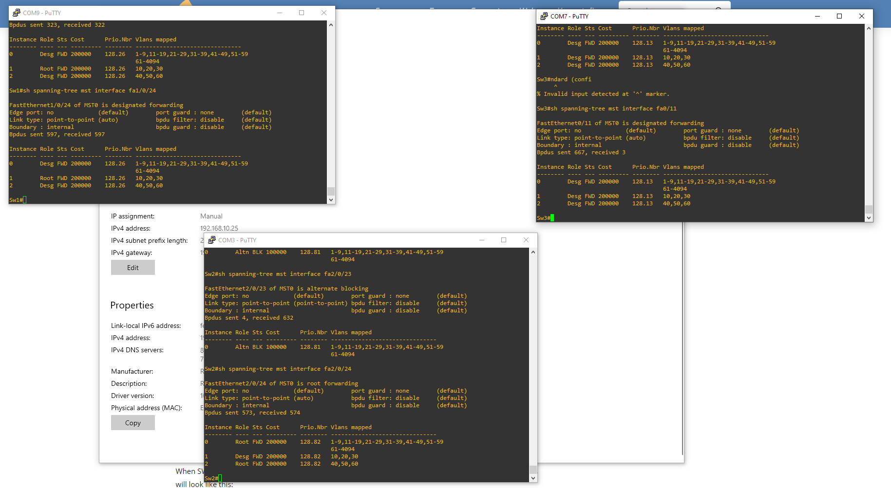
I’m struggling with MST. I follow the topic for MST and one of my switches has the interface role alternate for instance 0 and doesn’t see any other two instances. It’s the port fa2/0/23 on Sw2.
What could cause that issue?
Hello Krzysztof
Hmm, that does seem strange. I labbed this up to It seems that this interface is not recognizing MST on the other end of the link. I suggest you take a look at the interconnectivity you have set up between the switches.
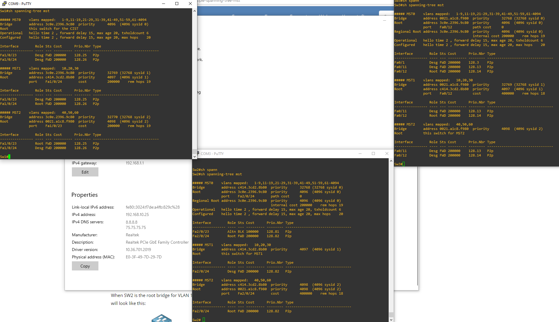
In your output of show spanning-tree mst on SW2, only port Fa2/0/24 appears. it seems port Fa2/0/23 is not participating at all in MST. Also, I see that SW1 has Fa0/12 as the root port for both MST0 and MST1 which should not be the case. This tells me that for some reason the connection between SW1 (Fa0/11) and SW2 (Fa2/0/23) is not correct.
Check this connection as far as trunk configuration goes as well as allowed VLANs, and correct physical connection (connected to the correct ports) and get back to us.
I hope this has been helpful!
Laz
Hi dear team.
- Regarding the MST Instance 0, I did not understand when you say that IST is Rapid Spanning-Tree that run within MST.
- Regarding the MST Root Port election, PVST+ BPDUs requires a priority at least 4096 lower than the PVST+ VLAN 1 BPDU. Which calculations are involved here?
- Regarding the compatibility matrix, what type of STP are compatible and how are the interactions?
Hello Zacarias
MST can be considered framework that allows for the organization of multiple instances of STP to function in an efficient manner by grouping them into instances. The actual STP mechanism that runs within each instance is Rapid Spanning Tree (RSTP). This is the case for both the IST, as well as all MST instances.
I assume you mean root bridge election. Remember that the bridge ID for any STP configuration is composed of the priority and the MAC address. But the priority itself is composed of a value between 0 and 61440 but in multiples of 4096. Why in multiples of 4096? Because PVST+ uses the system ID extension as part of the bridge ID. This is just the VLAN number. So if you’re using VLAN 24, and a priority of 4096, then the bridge ID is 4096+24 = 5020 plus the MAC address. For VLAN 25 PVST+ will use an ID of 5021 plus MAC address. So again, why 4096? because VLAN numbers range from 0 to 4095, and there must be enough “room” between priorities to fit in all possible system IDs or VLAN numbers.
So when MST listens to PVST+ BPDUs it receives on its boundary interface, it checks to see if they are superior compared to the VLAN 1 BPDU from PVST+. If they are superior, then the interface will be blocked and will show a broken state.
For this reason, PVST+ BPDUs must have a priority that is at least 4096 lower, in order to ensure that any VLAN value (between 1 and 4096) will not make the PVST+ BPDU superior, and result in a broken state.
Regarding the compatibility matrix, what type of STP are compatible and how are the interactions?
The following lesson is helpful for examining the interoperability between MST and PVST
You can find additional information about various types of STP at the following Cisco documentation.
I hope this has been helpful!
Laz
1 Like
Thank you Lagapides.
1 Like
Hello Guy,
I’m currently doing some labs related to MSTP and there is something that I need to investigate :
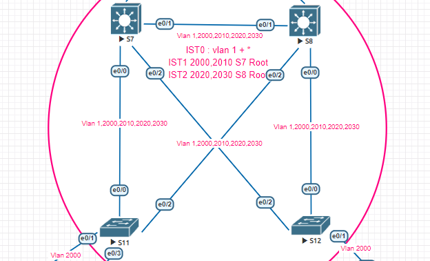
On S8, I just do a simple “int vlan 2020; shutdown”, following this one, I can see many flap on other vlan interfaces so I was suspecting some events on my mstp topology and with the debug on S7 :
S7#
*May 23 10:25:39.435: %AMDP2_FE-6-EXCESSCOLL: Ethernet0/3 TDR=0, TRC=0
S7#
*May 23 10:25:43.373: %VRRP-6-STATECHANGE: Vl2020 Grp 202 state Master -> Backup
S7#
*May 23 10:25:43.690: MST[0]: Et0/1 disputed
*May 23 10:25:43.690: MST[0]: Et0/1 state change forwarding -> blocking
*May 23 10:25:43.690: MST[1]: Et0/1 state change forwarding -> blocking
*May 23 10:25:43.690: MST[1]: Et0/1 disputed
*May 23 10:25:43.690: MST[0]: sending proposal on Et0/1
*May 23 10:25:43.690: MST[1]: sending proposal on Et0/1
I understand thanks to your course why I see the dispute message in my debug (after my action, BPDU received from S8 we can see port role changed from root to Designated) but I still don’t understand why this simple action on vlan interface number 2020 caused this mess.
Vlan 2020 belongs to MSTI 2. We can see the first notification is the vrrp role changement which is as expected.
Any clue on this one ?
Yoann
Hello Yoann
Thanks for posting, and welcome to the forum. Sorry for the late reply!
It seems that you are running into a common L2 IOU error that is often seen in GNS3, so the root of the problem is not associated with your MST configuration. However, since you are having issues with your L2 topology, MST is obviously adversely affected.
Can you try to replicate your topology using Cisco’s free CML sandbox?
I hope this has been helpful!
Laz
1 Like
Is there something that needs to be configured to use ISL with MST? I just tried to set up a simple virtual lab with three switches running MST. Using ISL (no encapsulation specified on the trunks), I could not get any traffic to go on non-native VLANs. Configuring the trunks for dot1q encapsulation fixed it.
Hello Michael
There are several parameters involved here, and one of them has to do with the platform on which you are configuring your topology. You mention that you are using ISL, and no encapsulation is specified on the trunks. Depending on the platform, this will have different results. Most modern platforms use dot1q by default, so if you don’t specify the ISL encapsulation, dot1q is being used. If you want to use ISL, you must specify the switchport trunk encapsulation isl command on the trunk.
Now without knowing more about your configuration, it is difficult to determine why your topology didn’t function, however, MST does indeed interoperate with ISL trunks. You can think of the two as separate entities that are not directly dependent.
Can you give us a little more info on your topology so we can help you in the troubleshooting procedure?
I hope this has been helpful!
Laz
1 Like
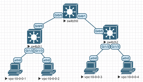
Thank you for the reply, @lagapidis ! A topology diagram and code snippets are below.
I am using virtual switch software that defaults to ISL. Here is what I see:
- Each trunk comes up with encapsulation n-isl.
- Each of the four PCs is on VLAN 2.
- With n-isl encapsulation, PC 1 can ping PC2, but not PC3 or PC4.
- With n-isl encapsulation & all PCs on the native VLAN 1, all pings work.
- With dot1q encapsulation & all PCs on VLAN 2, all pings work.
I don’t necessarily need to run ISL. I am just trying to understand how to get MST to work.
Michael
switch0#show run
!
spanning-tree mode mst
spanning-tree extend system-id
!
spanning-tree mst configuration
 name test-region
 revision 1
 instance 1 vlan 2
!
spanning-tree mst 1 priority 24576
!
!
interface GigabitEthernet0/0
 switchport mode dynamic desirable
 negotiation auto
!
interface GigabitEthernet0/1
 switchport mode dynamic desirable
 negotiation auto
!
end

switch1#show run

!
spanning-tree mode mst
spanning-tree extend system-id
!
spanning-tree mst configuration
 name test-region
 revision 1
 instance 1 vlan 2
!
!
interface GigabitEthernet0/0
 negotiation auto
!
interface GigabitEthernet1/2
 switchport access vlan 2
 negotiation auto
!
interface GigabitEthernet1/3
 switchport access vlan 2
 negotiation auto
!
end

switch2#show run
!
spanning-tree mode pvst
spanning-tree extend system-id
!
!
interface GigabitEthernet0/0
 negotiation auto
!
interface GigabitEthernet1/2
 switchport access vlan 2
 negotiation auto
!
interface GigabitEthernet1/3
 switchport access vlan 2
 negotiation auto
!
end
I found my answer, @lagapidis. I am using a switch license from CML (vios_l2-ADVENTERPRISEK9-M). Other users on the CML forum are reporting that ISL isn’t working for them. I was unable to set up a simple trunk using ISL, but it worked with dot1q. So, I will have to remember to use dot1q encapsulation when I am using this virtual IOS code.
Hello Michael
Great to hear, and thanks so much for sharing your experience. Such information is really useful to all those using the form. Your contribution is much appreciated!
Thanks again!
Laz
Hi,
I am a little bit confused that, when a root bridge is selected on the basis of Root ID, how there could be two root bridges in the same topology. If VLANs are different then the MAC addresses will remain the same with the same priority. Please guide.
Hello ntlipcore
By default, the root bridge is chosen based on root ID which is based on the MAC address. If you were to leave the default configuration, then yes, you would have the same device become the root bridge for all of the MST instances, and thus, for all of the VLANs.
However, it is possible, and desirable, to be able to change which switch will function as the root bridge for which MST instance. This can be configured using the priority command as it is described in the lesson.
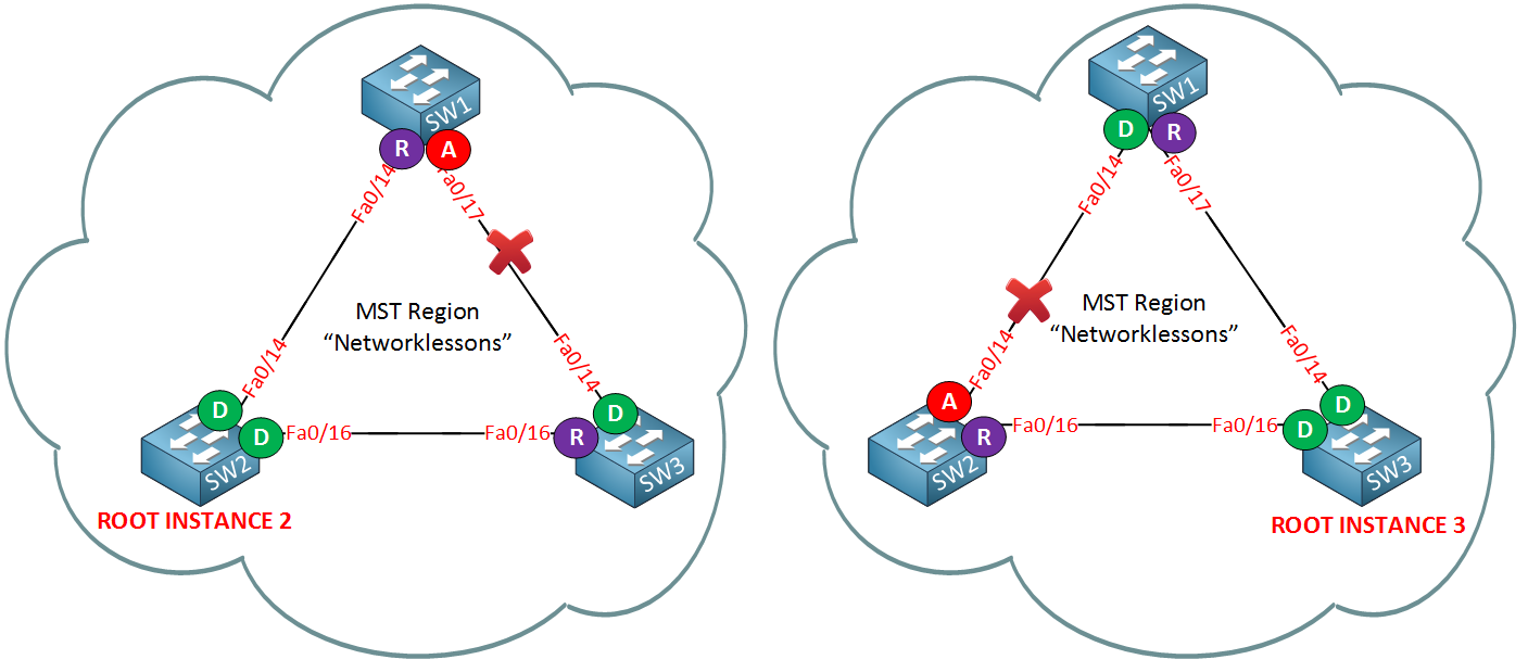
In the configuration in the lesson you will see that SW2 is configured as the root bridge for instance 2, and SW3 is configured as the root bridge for instance 3 of the MST configuration. This is done using the following commands on each switch respectively:
SW2(config)#spanning-tree mst 2 priority 4096
SW3(config)#spanning-tree mst 3 priority 4096
This results in two MST topologies on the same infrastructure with the following characteristics:
I hope this has been helpful!
Laz
1 Like
Hello Rene.
I really thank for your lesson and I very clear understand. I have one question.
How can I configuration for VPC and MST. I have two number of Cisco Nexus switches, these are running with VPC. And six numbers of Cisco catalyst are connect to the Nexus switch with two physical link. I would like to configure MST in these catalyst switch. It can be done ?
Hello Myo
Yes, it can be done. However, there are some special considerations that you have to take into account when employing MST with vPCs on Nexus platforms. The following document describes them in detail and is an excellent resource for doing exactly what you want to achieve:
I hope this has been helpful!
Laz
1 Like