Hi Networklessons
When I configure MST on my switches, all the features that I have in RPVST is inherit into MST?
Hello Rodrigo
Take a look at this lesson which describes how MST and PVST+ interact with each other. If you still have specific questions that are not answered there, please let us know!
I hope this has been helpful!
Laz
there were u define the spanning-tree priority for instance 2 u wrote
spanning-tree mst 3 priority
change pls to 2 instance
same for intstance 1
Hello Konstantinos
In the original diagrams, Rene indicates that there is an instance 0, instance 1, and instance 2, however from the beginning of the configuration of MST, he uses instances 0, 2, and 3. The rest of the lesson is correct. I will let Rene know to make the clarification.
Thanks for that!
Laz
I updated the lesson so that I use instances 0, 1, and 2 everywhere. I also included the configuration examples.
Hi Rene,
Amazing content in this page, but I’d like to understand more about the revision number, is like the ACL entries?, I gues if I make a configuration with higher number it will replace my last configuration right?
Hello MIchael
The MST revision number is one of the attributes used to identify a unique MST region. It is a construct that can be used by administrators to ensure that the configuration is the same on all switches in the region.
The idea is that every time you make a change to the MST configuration on a switch, you increment the revision number by one on that switch. In order to get the rest of the topology to sync up to that change, you must go into each switch in the region, and increment the revision number by one. This is a manual process and can be cumbersome especially if you have many switches.
My personal opinion (and one that others share as well) is that this is an outdated way of ensuring conformity across all MST switches. In practice, the revision number is maintained the same simply because it is inefficient to use this method of ensuring configurations are the same throughout the region.
I hope this has been helpful!
Laz
1 Like
Thank you Laz, I got it, is equal to vtp revision number, but in this case I have to configure manually in all switches.
Correct me if I’m wrong, I only have to change the revision number and everything is configured, or at the same time I will have to change the revision number as well as the new config.
Hello Michael
The accepted process is:
- Make changes to the MST configuration on the switch
- Increment the revision number on that same switch
- Go into all the rest of the MST switches in that MST region and increment the revision number so that it matches the number configured on the first switch.
I hope this has been helpful!
Laz
1 Like
Hi Rene,
When you say outside the region is seen as one big switch, does that mean if you were to look at the IST BPDUs being sent outside of the region (from a boundry port) the Bridge ID would be the same no matter which switch it was sent from? And if so, what bridge ID would it use from the region, the root? Thanks.
Hello Samir
Yes that is correct.
The bridge ID of the root bridge in the IST.
Take a look at this lesson.
If you go through it step by step, you will see that the bridge ID for the “imaginary big MST switch” that is seen by switches outside of the MST is indeed the bridge ID of the root bridge of instance 0 or the IST.
I hope this has been helpful!
Laz
1 Like
Hi Laz,
Yes it has, thanks.
Sam
1 Like
Here’s VLAN 10 which is mapped to instance 1. SW4 sees SW1 as the root bridge for this VLANeven though we configured SW2 as the root bridge for instance 2.
Hi Team,
I think there is a correction required in the above sentence as SW2 is the Root bridge for MST instance 1 and not for 2. It is SW3 which is the Root bridge for MST instance 2.
Hello Rahul
Yes, thank you for catching that I will let @ReneMolenaar know to make the appropriate changes.
Laz
1 Like
Can you elaborate on this point please: “by mapping groups of VLANs together that require the same topology”? On what basis do one group VLANs together? Against what criteria do we group VLANs together?
Thank you.
Hello NetworkGuy
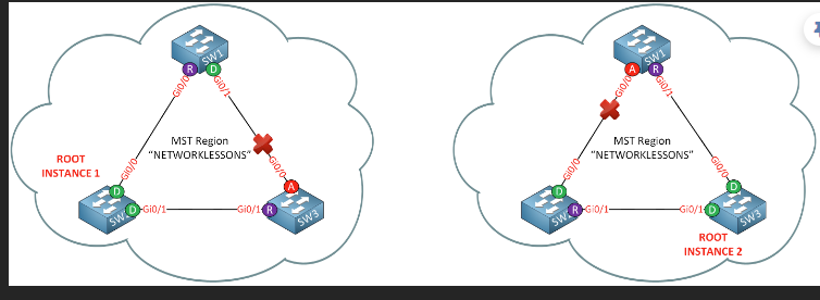
Take a look at this network topology:

There are only so many possible STP logical topologies that you can have. For example, the possibilities are:
- SW1 is the root with Gi0/1 of SW2 as the blocked port
- SW1 is the root with Gi0/1 of SW3 as the blocked port
- SW2 is the root with Gi0/1 of SW1 as the blocked port
- SW2 is the root with Gi0/0 of SW3 as the blocked port
- SW3 is the root with Gi0/0 of SW2 as the blocked port
- SW3 is the root with Gi0/0 of SW1 as the blocked port
Now imagine that you have 100 VLANs configured on these switches. With PVST+ you will need 100 instances of STP. Those instances will necessarily match one of the above 6 logical STP topologies. That means that you will have multiple instances of the same logical STP topology.
MST groups VLANs that share the exact same logical STP topology, thus needing only 6 instances of STP rather than 100. Does that make sense?
I hope this has been helpful!
Laz
1 Like
Hi Laz, amazing stuff! I suppose in MST, 6 instances would mean six groups of VLANs? Each would have a logical topology of its own? As for PVST each vlan would have its own instance, meaning own logical topology (one of the six possible logical topologies), plus each VLAN would broadcast a BPDU for every X seconds (100 VLANs X 100 BPDUs), correct?
Thank you.
Hello NetworkGuy
Yes, that’s exactly correct! You can quickly see how the MST solution is much more efficient than the PVST option since you are duplicating topologies to a great degree, and thus wasting device resources.
I hope this has been helpful!
Laz
1 Like
Hi,
There are few correction and clarification needed.
Below it says we are configuring SW4 but in the commands it shows as SW3.
And we’ll configure the GigabitEthernet0/0 and 0/1 interfaces of SW4 as trunks:
SW3(config)#interface GigabitEthernet0/0
SW3(config-if)#switchport trunk encapsulation dot1q
SW3(config-if)#switchport mode trunk
SW3(config)#interface GigabitEthernet0/1
SW3(config-if)#switchport trunk encapsulation dot1q
SW3(config-if)#switchport mode trunk
When SW4 is added to the topology, it sees SW1 as the root for VLAN 1 which is fine as SW1 is the root for VLAN 1 which is mapped to IST. However, when checking root for VLAN 10 on SW4 below statement does not make any sense. Please check:
Here’s VLAN 10, which is mapped to instance 1. SW4 sees SW2 as the root bridge for this VLAN even though we configured SW3 as the root bridge for instance 2. This is perfectly normal because MST will only advertise BPDUs from the IST to the outside world. We won’t see any information from instance 1 or instance 2 on SW4.
Thank you!
Hello Rahul
Yes you’re right, and thanks for catching that. That’s a typo in the configuration output, it should be SW4. I’ll let Rene know to make the change.
The statement should read:
Here’s VLAN 10, which is mapped to instance 1. SW4 sees SW1 as the root bridge for this VLAN even though we configured SW2 as the root bridge for instance 1. This is perfectly normal because MST will only advertise BPDUs from the IST to the outside world. We won’t see any information from instance 1 or instance 2 on SW4.
The intent of the statement is to show that a switch outside of the MST topology, such as SW4, that connects using PVST, will receive BPDUs from the IST. Since the IST BPDUs are showing SW1 as the root bridge, SW4 will also use SW1 as the root bridge for VLAN 10. This is done in spite of the fact that within the MST topology, VLAN 10 belongs to instance 1 which has a root bridge of SW2. I will let Rene know to make the necessary adjustments to this statement as well…
Thanks for pointing those out!
I hope this has been helpful!
Laz