Thanks Laz,
EPC is great on IOS-XE platform, a bit complex on IOS.
But I found that we lack of some informations on packet capture. for example, when logging IP NAT, you can clearly observe when IP @ have been translated. I will try the ACL Log method to see.
Thanks
1 Like
Hello Thierry,
I’m doing good here, we are safe. I hope you as well?
I agree this is a good idea. I think I’ll include it in every configuration now. Throughout the years, it happened multiple times that something worked on version X, but didn’t work or had different behavior on version Y.
Rene
1 Like
Hi I have a question, in the NAT virtual interface, almost at the end of the video, if you are sending a ping from R3 to 192.168.23.1, why the ping goes til R1 ? if the ping was meant to 192.168.23.1, I think my question is why it the debugs we see that the ping goes till R1 if R1 is suppossed to be out of the picture, thank you in advance
Hello Armando
Remember that in that particular configuration, the 192.168.12.1 address (R1) is being translated to 192.168.23.1 (global address of R1) and visa versa. So when R3 pings 192.168.23.1, it reaches R2, and the NAT config translates it to 192.168.12.1 which is R1.
The purpose of the lab was to reach R1 from R3 using the 192.168.23.1 address. The process reaches R1 because of the NAT translation.
I hope this has been helpful!
Laz
1 Like
Can I do Virtual NAT over port channel? specifically on Catalyst 9500?
According to the Cisco documentations they’re saying I can’t do NAT, they haven’t mentioned virtual nat!
I was trying to NAT my uplink to the ISP
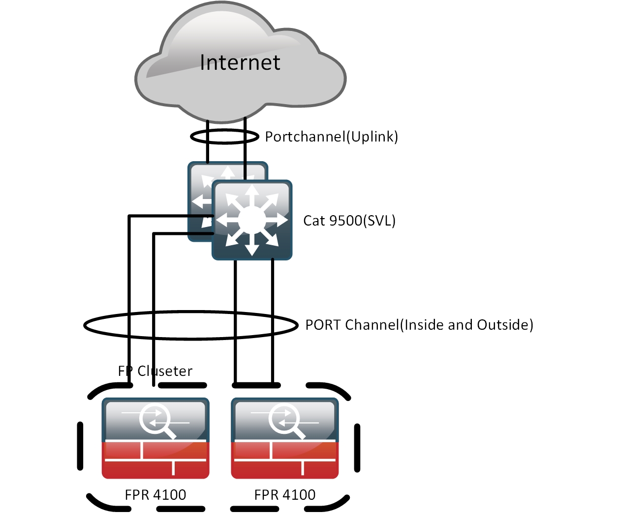
so I just found that we have two ASRs 1001-x instock, now I have a different question, the throughput on these routers are determined based on the license you buy? and since the ASR 1k doesn’t support nVR clustering how should I make my uplink port channel-ed across the chassis(for redundancy)?
Hello Erik
Looking at the documentation you linked to, I don’t see where it says that you can’t do NAT. Actually, I see that you can do NAT. Concerning virtual NAT, I haven’t attempted it on the specific platform, but I have the impression that it is not supported. Looking at this Command Reference for the Catalyst 9500 I was unable to find the command ip nat enable which seems to indicate that it is not supported.
Virtual NAT is a feature that you would use more often on an edge router rather than a switch like the 9500 so it makes sense that you won’t find it on such a switch model.
Yes, by default, the available system bandwidth is at 2.5Gbps and is upgradable to 5 Gbps with a software-activated upgrade license.
Depending on what your routers are connecting to on the ISP side of the link, you have several options including dual-homed BGP connections, using a gateway redundancy protocol, or simply employing dynamic routing that can employ equal or unequal cost load balancing. There is no way to implement a port-channel-like implementation with the specific devices.
I hope this has been helpful!
Laz
1 Like
(post withdrawn by author, will be automatically deleted in 24 hours unless flagged)
Good Job. Amazing lessons !!
Regarding the domain-based Nat router, you demonstrated that in order to overcome the un-successful ping from R3 to R1, we solved it by inserting the “add-route” parameter into our NAT command; But what was the running config on R2, JUST BEFORE the “add-route” was added to the Nat command.
By comparison, ping from R1 to R3 was quite successful, I understand it was purely relying on RIB routing, there was no Nat entries at all in the debug. I wish to go further, to compare why ROUTING was successful in this case, and not for other cases; What had prompted R2 to do the successful routings? for the ping traffic (back and forth), especially in the absence of a default (static) route.
Hence I would be grateful to see R2’s running config. (Terribly sorry , I understand the above lessons was to illuminate the NAT mechanisms only, not routing ).
For your ease of understanding , let me explain my question further: When R2 ROUTED the ICMP traffic successfully, was it because we had configured on R2, those two set of Nat rules ( namely, ip nat outside source static 192.168.23.3 192.168.12.3 ; AND ip nat inside source static 192.168.12.1 192.168.23.1 ) , thus even with no default (static) route , ping from R1 to R3 (and back) could route successfully.
After all, RIB updates were derived from the control plane, therefore if we were to configure on R2 any Nat rules, then R2 will know very well how to send the Ping traffic (back and forth) , with ease.
Many Thanks as always for your time , and amazing articles !
Hello Jenny
If you take a look at the starting configs indicated at the beginning of the lesson, and make the appropriate changes to those configs indicated in the lesson, you can reconstruct the config of R2 just before the add-route command was added. Specifically, you would have this:
hostname R2
!
ip cef
!
interface GigabitEthernet0/1
 ip address 192.168.12.2 255.255.255.0
 ip nat inside
 no ip route-cache
!
interface GigabitEthernet0/2
 ip address 192.168.23.2 255.255.255.0
 ip nat outside
 no ip route-cache
!
ip nat inside source static 192.168.12.1 192.168.23.1
ip nat outside source static 192.168.23.3 192.168.12.3
!
end
Note that when the second NAT rule was added, and R1 pinged to 192.168.12.3, it did routing first. This means that R2 sent the echo reply to R1. Note Rene says in the lesson that “R2 receives the packet from R1, checks its routing table and routes the packet out of the same interface.” Routing was successful as an operation, because R1 is sending a packet to the same subnet as itself, so no default route is necessary. However, the desired behaviour was a failure.
Just to clarify, this ping was successful, but its path was a failure. It didn’t go R1 → R2 → R3 → R2 → R1 as desired, but it went R1 → R2 → R1.
I hope this has been helpful!
Laz
1 Like
You are awesome Laz ! Thank you for your excellent explanations !
Sorry about my newbie’s question. I now have one question left only.
At the beginning, when R3#ping 192.168.23.1 repeat 1 , I could understand in the debug that, R2 upon receiving this traffic on its outside interface, nat translation immediately kicked in , and then the traffic header’s source address was natt’ed from 23.3 to 12.3.
Thus, according to the debug, I could see only the SECOND nat rule was performed on R3, ie 23.3 was natted to 12.3, because traffic was going from “outside to inside”. So far, up to this point, First Nat rule did not kick in, according to the debug. ( I am going by the debug).
If the FIRST nat rule did not kick in, then what happened next was a mystery to me, “R2 just looks up the routing table and forwards it towards R1”. Could you kindly explain, how did R2 figure out that , this traffic’s header destination address should be 12.1, not 23.1. At this point, I do not wish to look at the ICMP’s return traffic as yet; I am just focusing on, how R2 forwarded the packet to R1;
Namely, I am interested in R2’s routing table lookup.
Exactly how did R2’s routing table figured out that 23.1 was meant to be “translated” into 12.1.
mmm… Because I could not see from the attachment debug, when did R1 gets TRANSLATED from 23.1 to 12.1 ?
Thanking you very much for your wisdom and patient.
Best regards
jw
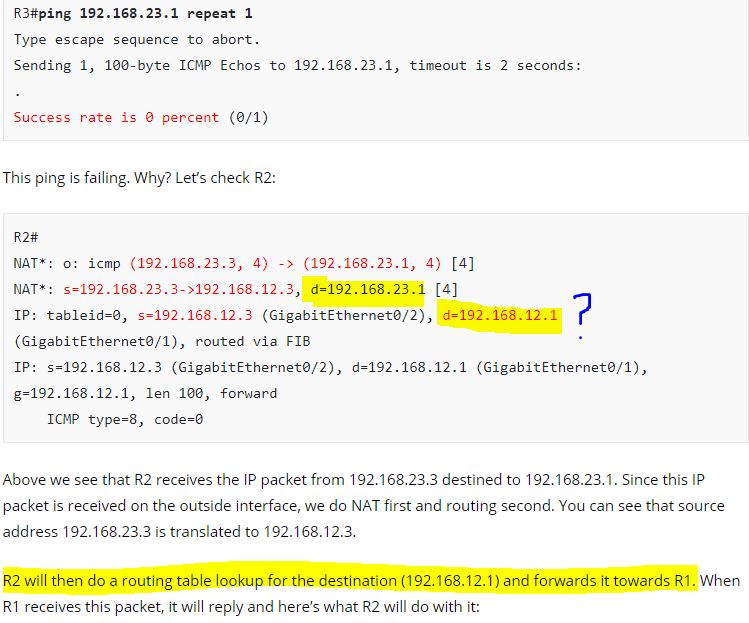
Hello Jenny
This is determined using the ip nat inside source static 192.168.12.1 192.168.23.1 command. You will notice that in Rene’s lesson titled IP NAT inside source vs IP NAT outside source, he says the following:
The
ip nat inside sourcecommand:
- Translates the source IP address of packets that travel from inside to outside.
- Translates the destination IP address of packets that travel from outside to inside.
So in this case, the second point took place, namely, the destination address of 23.1 was translated to 12.1. The truth is that the debug is not so clear on this, but what you have highlighted in your post above is essentially the translation.
I hope this has been helpful!
Laz
1 Like
Aha Laz ! Thank you for those thought-provoking examples in your articles !!
1 Like
In the clip 3:05
NAT: i: icmp (192.168.12.1, 11) → (192.168.23.3, 11) [19]
Just would like to ask any idea what the number 11 and 19 represents? Is one of them the port used for NAT? Thanks.
Hello Yat
The output you see is a result of the debug ip nat detailed command. The value that appears after the IP address and a comma, which in your example is the value “11” is the Transport layer port that is used. So in this particular case, the ICMP packet is using port 11.
Now the value in square brackets, which in your example is 19, is an IP identification number of the packet. This is the value found within the Identification field of the IP header. It is used to aid in the fragmentation and reassembly of an IP packet. In the NAT output, it is displayed as part of the output of the debug in order to more easily identify and correlate with other packet traces from protocol analyzers.
I hope this has been helpful!
Laz
Thanks for this Laz. I was just labbing this up and noticed the extra line in the debug which I think fills in the missing piece of the puzzle.
So it looks like there is a double NAT translation going on, due to the 1st NAT (inside source static) rule.
*Oct 31 14:16:02.723: NAT: o: icmp (192.168.23.3, 3) -> (192.168.23.1, 3) [7]
*Oct 31 14:16:02.723: NAT: s=192.168.23.3->192.168.12.3, d=192.168.23.1 [7]
***Oct 31 14:16:02.723: NAT: s=192.168.12.3, d=192.168.23.1->192.168.12.1 [7]**
*Oct 31 14:16:02.723: IP: s=192.168.12.3 (Ethernet0/2), d=192.168.12.1, len 100, input feature
1 Like
It looks like that Virtual NAT is not supported by 7200. Or at least I don’t find the IP NAT ENABLE command on the IOS 15 version I installed on GNS3. But I find the command on the 3600 IOS 12 version
Hello Giacomo
When examining what features are supported for a particular router, it’s important to remember that features are both IOS specific as well as platform-specific. NVI was first introduced in IOS release 12.3(14)T, so routers that have this release or later are expected to support NVI. However, the 7200 platform is a very old platform, and was initially released before 1999! It has been end-of-sale (EOS) since 2012 and end-of-support (EOS) since 2017.
Looking at the archived data section of the Cisco Feature Navigator, the NVI is not one of the supported features of the 7200 series platform. So even though you may be using a version 15 IOS, the platform itself doesn’t support it.
This is why you can see the NVI feature in version 12.3(14)T or later on the 3600 but not on version 15 on the 7200.
I hope this has been helpful!
Laz
So would virtual NAT be the best method if I have an edge ISR CE router used to connect to an MPLS network from a newly acquired company using a different private subnet range. I want to NAT the acquired company private range at the ISR CE Edge to a private subnet available from the parent company range then route out over the new ISP MPLS ckt at the acquired branch back into the parent company network with the new parent company subnet.
Hello Chad
NAT would be a solution for any case where you have a certain subnet that you want to translate to a different set of addresses. This is useful in cases where companies are merging and subnets overlap and need to be harmonized.
Now whether you will use traditional NAT or a NAT Virtual Interface is really up to you. The NAT Virtual Interface is more elegant in its configuration, and can indeed be used. Now the more pertinent question is can it be used on the actual CE device of an MPLS network? Yes, it can be done, and it is considered a tried and tested method.
For your specific situation, in order to get into more details, we’d need further information about the topology, but in principle, yes, it would work.
I hope this has been helpful!
Laz
1 Like
Hi, in the post, there is one part which says “The example above doesn’t work on IOS 15.x”
So, how do you make it work for IOS 15.x ??
I tried to lab it up, and like you said, the route being added by “add-route” is overruled by the “host route” on R2:
L 192.168.12.3/32 is directly connected, GigabitEthernet0/0
And as a result, the below command still fails:
R3#ping 192.168.23.1