This topic is to discuss the following lesson:
Hi Rene,
So far I know we dont use src rewrite for Outside NAT . For outsite NAT ,We use Port forwarding to a particular IP(Dont translate SRC IP Just rewrite DST IP).So how the problem occure .I think no issue on Legacy NAT or do me more explanation in which situation, we will use NAT Virtual Interface.Thanks
br//
zaman
Hi Zaman,
The most common NAT setup is to translate from inside to outside, translating only the source IP address. Port forwarding is also very common.
It’s unlikely to see this example often in a production network but understanding the “order of operation” might be important for CCIE R&S students.
The configuration of the NAT virtual interface might be a bit simpler. One problem though is that one some routers, it’s performance is worse than “legacy NAT” so that is something to check.
Rene
1 Like
Awesome (Y)
This article is important, for having a good understanding of NAT.
I do understand that the real issue is : How to reach a WAN address from a LAN domain, by pinging a LAN address (that is supposed to be translated to the target WAN address). I do also understand that the solution is not supposed to use routing rules for jumping from LAN side to WAN side.
However, some points are confusing for me.
- Point-1
The issue is first demonstrated by typing the command below :
R1#ping 192.168.12.3 repeat 1
But ; the following explanation lines do no longer use it. Instead, the command below is always used (until the begining of the section “NAT Virtual Interface”) :
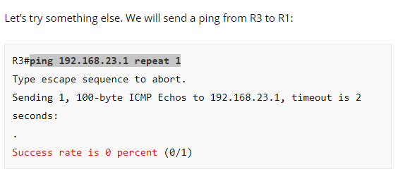
R3#ping 192.168.23.1 repeat 1
- Point-2
Hard to see (in the debug ouptut) the difference between using “add-route” or not-using “add-route” !
- Point-3
The text below lets suppose that it takes two “ip nat source static” commands for the configuration of NVI.
Now let’s convert our old two NAT commands into new NAT commands:
R2(config)#ip nat source static 192.168.12.1 192.168.23.1
R2(config)#ip nat source static 192.168.23.3 192.168.12.3
- Point-4
In the command below :
R2(config)#interface range GigabitEthernet 0/1 - 1
I would say “2” at the place of the last “1”
- Point-5
The first NVI configuration example (Static NAT) does not show that the initial issue has been solved. Again, why do the command below is not tried again ?
R1#ping 192.168.12.3 repeat 1
Hello Maodo
The command ping 19.168.12.3 repeat 1 is used to test if a NAT translation without a default route will function correctly.
The command ping 192.168.23.1 repeat 1 is a completely different test. which is testing the NAT translation between 192.168.23.1 and 192.168.12.1. This can be seen from the words: “Let’s try something else…” before the command as seen below:
Secondly:
There is no difference in the debug output for when the ping goes from R3 to R1. The difference is on the return of the ping. On the return of the ping, with no add-route command, there is no indication of a NAT translation, whereas with the add-route command, the translation occurs correctly.
With these two commands, we are implementing the TWO NAT translations that were implemented in the first section. These are two separate NAT translations creating two separate NVIs.
Yes you are correct, this should read interface range GigabitEthernet 0/1 - 2 I will inform @ReneMolenaar
With the NVI, this problem will have been solved. You can lab it up, test it out and let us know your results!
I hope this has been helpful!
Laz
1 Like
Rene,
Regarding NAT VI I noticed a limitation I am having when configuring this and I was wondering if you can shed some light on this.
First off, great explanations and examples of NAT VI. Network Lessons has definitely been one of my go to sources for studying and I have been recommending this site to co-workers which find this site amazing as well.
Back to my question:
When I configure NAT VI I can test my nat translations from within my LAN hitting my WAN ip address ex: (12.1.1.1 port 80) but why can I no longer remote into that device through its local IP ?
From the example given below from 10.1.1.4 I can remote into 10.1.1.2 by hitting 12.1.1.1 port 80 but I cant remote into it locally by 10.1.1.2 80 which does work with domain NAT defining inside and outside interfaces.
ex:
LAN network 10.1.1.0/24
WAN network 12.1.1.0/24
nat translation:
ip nat source list NAT interface FastEthernet0/0 overload
ip nat source static tcp 10.1.1.2 80 12.1.1.1 80 extendable
ip nat source static tcp 10.1.1.4 443 12.1.1.1 443 extendable
Thanks in advance.
Hello Juan
From my understanding, this is your topology (correct me if I’m wrong:
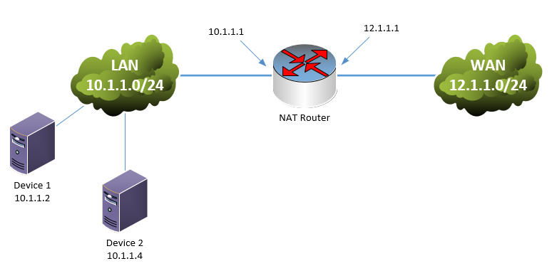
You are translating:
- 12.1.1.1:80 on the WAN interface to 10.1.1.2:80
- 12.1.1.1:443 on the WAN interface to 10.1.1.4:443
So, you are able to remote into Device 1 from Device 2 ONLY when you connect via the 12.1.1.1:80 address and you cannot connect when you attempt to connect directly to 10.1.1.2. Correct?
If this is the case, then the NAT configuration has nothing to do with the problem. Any communication between Device 1 and Device 2 using the 10.1.1.0/24 IP addresses will be directly between them. So the only thing I can suggest is that there is an access list or a firewall rule on device 1 blocking any connectivity to it from a source address of 10.1.1.4.
Take a look at any such configuration and let us know your progress…
I hope this has been helpful!
Laz
Thanks Laz for the quick response. Great diagram depicts exactly what I was labbing. Its strange that it doesn’t work i did this in a lab enviroment with very basic configs. I Just ip’d the interfaces and setup up nat. The strange part is that it works perfectly fine using domian nat defining inside and outside interfaces. But once i remove those commands and add ip nat enable on the interfaces unless i define the mapped ip in this case 12.1.1.1 port 80 i cant remote into the device anymore using its real IP which is why i thought it was an NAT VI limitation.
1 Like
Thanks Rene.. that was lucid and laid threadbare.. commendable effort mate.
I have a general question. For this demo you had turned off Fast Switching by no ip route-cache and your debugs show routed via RIB .
Is it safe to say.. all NAT traffic will be punted to CPU, as IP addresses on the NAT devices are involved?
Thanks,
Ayyappan
Hello Ayyappan
The quick answer is “it depends.” Really it depends on the platform. For the Catalyst 6500 switches with 720 supervisors, for example, NAT is handled in hardware while with Supervisor 1 and 2, NAT is software switched.
According to the following Cisco documentation,
“Cisco IOS NAT supports Cisco Express Forwarding switching, fast switching, and process switching.”
Regardless, the fact that the no ip route-cache command has been applied does indeed mean that all packets entering the layer-3 interface will be process switched by the CPU instead of hardware, whether NATed or not.
I hope this has been helpful!
Laz
2 Likes
Hi Team,
Can you please explain more about Match-in-VRF Support for NAT. Cisco documentation on this topic is hard to digest ![]() It would be great if you can elaborate using below example
It would be great if you can elaborate using below example
ip nat inside source static 10.10.10.1 172.16.131.1 vrf vrf1 match-in-vrf
Hello Aniket
First of all, it is important here to clarify what kind of scenario we are talking about when we speak about VRFs. This is described as follows in Cisco documentation:
Virtual Private Networks (VPNs) provide a secure way for customers to share bandwidth over an ISP backbone network. A VPN is a collection of sites sharing a common routing table. A customer site is connected to the service provider network by one or more interfaces, and the service provider associates each interface with a VPN routing table. A VPN routing table is called a VPN routing/forwarding (VRF) table.
When you have multiple VRFs, there is the possibility of having the same address space connected to multiple VPNs of a router. So you may have the 10.10.10.1 address exist in one network, which is routed using the routing table of VRF1, and you may have the same address in another network, which is also routed by this router, but in VRF2. That’s fine and it should work well.
But what if you want this same router to perform NAT on these particular IP addresses? They are both the same, so if you simply use the following command:
ip nat inside source static 10.10.10.1 172.16.131.1
…then both hosts with this IP address will be translated to the same outside address. This however will not work.
You can enable VRF awareness onNAT by adding the VRF to which each translation should be mapped. This way, internally identical IP addresses on different VRFs, when NATted, will obtain unique global addresses.
But, what happens when you want these two hosts connected to two different VPNs, with identical IP addresses, to communicate directly with each other? Or to communicate with a subnet on another VPN that may have the same IP address range? This is where the match-in-vrf keyword comes in. It extends the VRF awareness of NAT such that inter-VPN communication can take place. In other words, communication from one VPN to another VPN on the same router can take place, using NAT.
What the keyword does specifically is, for inter-VPN traffic, it allows the translation of 10.10.10.1 to the required address in the other VPN while keeping track of which VRF it originally came from. Otherwise, inter VPN communication would not function, because 10.10.10.1 belongs to multiple VPNs.
I hope this has been helpful!
Laz
2 Likes
Thanks for an explanation Laz,
Still having doubt about the last section which you have explained. You said that match-in-vrf comes in picture where communication from one VPN to another VPN on the same router takes place, using NAT.Above that line you mentioned “intra-VPN” communication keyword. I believe you wanted to say “inter-VPN” communication ?
Hello Aniket
Yes you are correct, my apologies. It should be inter-VPN. I have fixed it in my post.
Thanks again!
Laz
Hello Rene,
Thanks for the lesson,
in the first example below:
R2(config)#ip nat inside source static 192.168.12.1 192.168.23.1
my question is: why the global IP address is 192.168.23.1 not 192.168.23.2?
Thanks in advance
Hello Wisam
It is possible to create a NAT rule that will translate using the actual assigned IP address of the outside interface of the NAT router, or, you can use an IP address that is not actually assigned to the outside interface, but is routed to that interface from the WAN network. In this case, the outside IP address being used is not the same as that of the outside interface. This will function correctly, as long as the WAN “knows” about this address and will route this address correctly to the appropriate router.
This is also the case when you have a pool of external IP addresses that are NAT’ed to internal addresses. They need not be assigned to the actual outside interface.
I hope this has been helpful!
Laz
2 Likes
Hi Rene & Co,
Thanks for the great content and I hope that all you are safe during this pandemic time.
Just to let you know that it can be very valuable if during your various demo you provide bit of informations about your environment like (IOS/IOS-XE/IOS-XR) version.
It’s little difficult when practice and don’t have the same result because IOS version are different for example.
I’m using IOS 15.7(3)M3 for this lesson and the debug output are very different with new terms like: FIBipv4-packet-proc, FIBfwd-proc… etc…
Thierry,
Best Regards
1 Like
Hi Rene & NL Team,
Please, I want to know if it’s possible to disable ip route-cache in “Cisco IOS XE Software, Version 03.16.09.S - Extended Support Release”…
I have the following message when I try to run no IP route-cache on an interface for debugging purposes. “Platform cannot disable ip route-cache on Port-channel interface”
Thanks.
1 Like
Hello Thierry
Disabling route caching on an interface will also disable CEF. On some platform/operating system versions it is not possible to disable CEF, such as is the case with your situation. In this case, in order to see the debug take place, you can do one of two things:
-
You can create an access list with a single permit any statement and include the “log” keyword. This will result in all packets being examined, and logged, and thus CPU switched. Such traffic will show up in the debugs. For example:
ip access-list extended MY_TEST
  permit ip any any log
- You can use Embedded Packet Capture (EPC) to capture the packets you want and to examine them accordingly. You can find out more about this at the following lesson:
Concerning your suggestion about specifying the IOS that Rene uses in his lessons, I will relay the information to him and let him know.
I hope this has been helpful! Stay healthy and safe!
Laz
2 Likes