can you please tell me how 2 switches are connecting to a single router interface in a single subnet…and ip adress on switches are management ip addresses or is it vlan ports…please help…
Thanks.
can you please tell me how 2 switches are connecting to a single router interface in a single subnet…and ip adress on switches are management ip addresses or is it vlan ports…please help…
Thanks.
Hello Sumant,
I will do my best to help. Packet tracer topologies are built using a “drag and drop” method. If you open packet tracer near the bottom left corner under the “time” you will see “network devices” If you click that, directly underneath you will see some sub-options. We will be using the first two. The circle with arrows is the router section and the square with the arrows is the switch section. First click the router section now to the right you will see all the routers available for use. Simply click and drag the router onto the topology portion of the application
(keep in mind packet tracer starts the router powered on so If you need to add any hardware you must turn the router off first.)
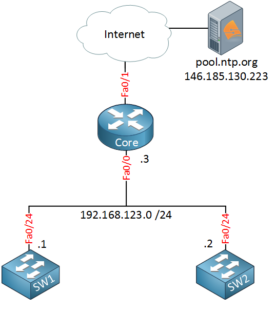
I suggest you use the 4321 or 1841 routers these are my favorites to lab with in packet tracer. Now that we have our router in the topology all we need is the switches and one server. If you click the switch icon right next to the router icon that we used earlier you should see all the switches available. This works the exact same way the router did just drag and drop the switches you want into the topology section. Use the 2960 switch unless you need to do layer 3 switching (in this topology no layer 3 switches exist) Now we just need the server. Earlier I mentioned that network devices are located underneath “time” Right next to network devices is “end devices” If you click this the proper sub-option is already selected. The third “generic” device from the left is the server we want. Drag and drop this into the topology section. Now, all we need to do is connect our devices together as shown in the diagram above. You can do this by selecting the button that looks like a lightning bolt. This is located near “time” and underneath “Power Cycle Devices” you need to select a straight through cable. Once you have selected the proper cable, click the device you would like to connect, select the interface to connect, now do the same on the other device. Do this until you have the topology desired.
Now if you need help with configuration commands, I could help you but that would not teach you anything. I would be more than happy to look at your config if you are having trouble getting NTP working properly, but make sure to give it your best go first!
Also keep in mind that packet tracer IS NOT IOS and LOTS of commands are missing, but if your in a pinch to lab it does the job. I would really consider trying to get some IOS images and GNS3, google is a good resource for this.
I hope this helps!
Scott
Hi kevin
Thanks for your prompt reply and detailed explanation.i think i am getting used to using the forum here.the only problem that is killing me about this topology is how 2 switches are connecting to 1 router interface and they all are in same subnet?
Are they using vlan or trunk??and the ip addresses on switch ports are management ip addresses or what?how switches are connecting to router and then sending ntp pkts to each other as well…
I stopped myself go further into ntp configurations before i clear this step..i think ntp configurations are not that hard if you know the topology…
Again thanks for your time…
Ahhhh I misunderstood! The cabling in the diagram is not accurate in the real world it is just a simple way to show that the router and switches are on the same subnet/broadcast domain. If you want to run this topology you can add another switch, this switch will connect to the router and the other two switches will be daisy chained to this switch. Technically you could also just daisy chain the two switches together and attach one switch to the router but this doesn’t reflect the topology desired as much as my first suggestion.
I hope this helps,
Scott
hi scott
thanks for your help.i tried the topology in packet tracer but i think you cant run ntp server ip
command on switches in packet tracer..so i tried ntp topology with 3 routers and a ntp server and it worked fine..
Thanks again…
That is good to know you cant configure NTP on packet tracer switches. Sometimes I only have access to packet tracer so knowing some of the caveats of the application helps a ton. Glad to hear you were able to lab this up!