I found this topic by accident while studying for SPCOR. I am not talking about having an ABR with interfaces in multiple areas, I am talking about a literal multi-area adjacency (one interface being in multiple areas)
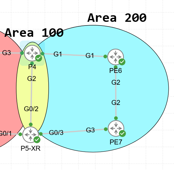
Take this as an example (don’t worry, the red area on the left is Area 0).
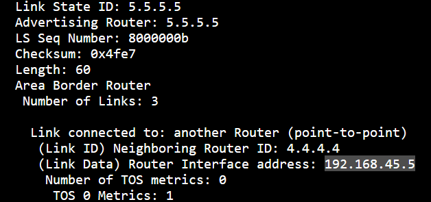
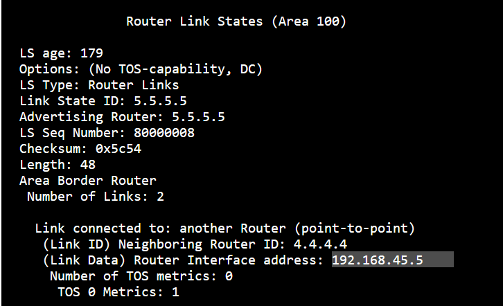
Documentation states that “A multi-area interface advertises an unnumbered point-to-point link in the device link-state advertisement (LSA) for the corresponding area”. I haven’t found this kind of entry in the LSDB.
Documentation states “It establishes a neighbor relationship with the corresponding multiarea interface on the neighboring device. A mixture of multiarea and primary interfaces is not supported”"
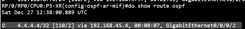
P5-XR has no multiarea interface, it only has the primary interface. P4 has a multiarea interface and yet it happily forms the adjacency with P5-XR despite one interface being multiarea and the other one being primary. Wasn’t the documentation saying this wasn’t possible? Or am I misunderstanding this?
From my research, I believe that this is simply a matter of badly written documentation (which is something you see occasionally in Cisco documentation). Based on RFC 5185 in sections 1.2 and 1.3, it talks about the multi-area interface feature and what it solves, and it referrs to the idea of the use of an unnumbered interface (an interface without any assigned IP address).
Multiple adjacencies are created between the routers, one in area 100 and another in area 200, based on your scenario. The idea that is being conveyed is that the primary adjacency (over area 100) functions normally, with a numbered interface, where the network of that interface is advertised normally using OSPF. The “secondary” adjacency (over area 200) will act as if it is on an unnumbered interface, meaning that it will NOT advertise the link’s network in OSPF. This doesn’t mean that you won’t see the IP address of the interface (since it is not configured as unnumbered), but it does mean that as far as OSPF is concerned, the link for that adjacency behaves as if it is created over a point-to-point unnumbered interface.
Again, I think that the way it is written can be easily misunderstood. With the changes to your configuration, you configured area 200 as the primary adjacency on both ends, and 100 as the multi-area adjacency only on P4. The result is that the adjacency across area 200 is working just fine, because it is properly configured on both ends! However, any hellos sent by P4 on area 100 will be dropped by the P5.
What the documentation is saying is that multi-area adjacency requires matching configuration on both ends for the secondary area(s). Both routers must share at least one common area to form an adjacency, which you have achieved using area 200. You CAN have asymmetric configurations (one side with multi-area, the other without) as long as they agree on the primary area. If you do this:
P4(config-if)#ip ospf 110 area 100
P4(config-if)#ip ospf multi-area 200
I have one more question that I thought about. Why is multi-area only allowed on P2P interfaces? I specifically had to configure my interfaces as P2P otherwise it refused to work.
This is actually by design, and you can see this explicitly stated in RFC 5185, which defines OSPF Multi-area adjacencies. It says that the interface type must always be point-to-point. Other interface types will not work.
That’s why you can’t configure it unless your interfaces are P2P. The question is, why has it been designed this way? The primary answer is that the entire LSA advertising model for multi-area adjacency is built around the P2P Type-1 link. Section 2.7 of the same RFC states that only Type 1 LSAs should be advertised in such an adjacency.
On a broadcast network, OSPF would normally generate a Type-2 Network LSA (originated by the DR). Multi-area adjacency deliberately avoids this. They only create a topological P2P stub entry. Supporting that model for multi-area adjacencies (i.e., broadcast network types) would make the feature much more complicated. The introduction of anything other than a Type 1 LSA on this type of interface would increase complexity (and because multi-access networks have fundamentally different characteristics), which is precisely why the recommended, clean design is to mandate P2P.
So this restriction is due to the RFC definition itself. It’s the clean design choice the RFC authors made to keep OSPF’s behavior consistent and avoid the topology model conflicts that broadcast networks would introduce. Once you set the network type to P2P, everything aligns perfectly. Make sense?