Thank you very much for answer. I’ll try to simulate this issue. Thank you for recommendation to set both router.
Best regards,
Marcin
Thank you very much for answer. I’ll try to simulate this issue. Thank you for recommendation to set both router.
Best regards,
Marcin
**R2:**
interface Loopback0
 ip address 1.1.1.1 255.255.255.0
!
interface Serial2/0
 ip address 192.168.123.1 255.255.255.0
 encapsulation frame-relay
 ip ospf network non-broadcast
 serial restart-delay 0
 frame-relay map ip 192.168.123.1 102
 frame-relay map ip 192.168.123.3 103
 frame-relay map ip 192.168.123.2 102
!
router ospf 1
 network 1.1.1.0 0.0.0.255 area 0
 network 192.168.123.0 0.0.0.255 area 0
 neighbor 192.168.123.2
 neighbor 192.168.123.3
!


**R1**
interface Loopback0
 ip address 1.1.1.1 255.255.255.0
!interface Serial2/0
 ip address 192.168.123.1 255.255.255.0
 encapsulation frame-relay
 ip ospf network non-broadcast
 serial restart-delay 0
 frame-relay map ip 192.168.123.1 102
 frame-relay map ip 192.168.123.3 103
 frame-relay map ip 192.168.123.2 102
!
router ospf 1
 network 1.1.1.0 0.0.0.255 area 0
 network 192.168.123.0 0.0.0.255 area 0
 neighbor 192.168.123.2
 neighbor 192.168.123.3
following is the Spoke 1, hub configuration . Hub,spoke1, spoke 2 ping each other. Why ip ospf neighbor
displays spoke 2 from spoke 1 as attempt state? debugging shows that r2 sends s ospf packet to spoke 1 and then mark it as dead. documentation and rene metnions to frame-relay map ip 192.168.123.1 201 br , the same and documentation mentions to boost the procedure of neighborship when there is no of it, so i am asking do i really have to use br on frame relay instruction in order to perform normal neighborship between the 2 routers or should i leave it as it is. Trying and the second choice(more logical - using br on frame relay instruction) since use broadcast to reply hub to spoke 2 packets but here the problem is on IP level, ospf not hearing ths UNICASTS hello packet to router 2. Could u please tell me wht will be the problem since i am able to ping each other router?
Basic question :
At the beginning of this lesson it says :
“If you select the non-broadcast network type then OSPF will assume you are running a multi-access network”
I know Frame Relay is NBMA, but Ethernet also is a multi-access network , OSPF choose broadcast network type to its interfaces (despite you have a p2p link between two routers)
So NMBA it is not the only multi-access network … please could you shred some light on this issue ? Thanks in advance.
Hello Konstantinos
First of all, the Attempt state is a state that is only valid for manually configured neighbors in an NBMA environment, just like in your case. During the Attempt state, the router sends unicast hello packets every poll interval to the neighbor. If the state persists, that means that hellos have not been received from the neighbor within the dead interval.
More info on the Attempt state can be found here:
Now why is your topology stuck in Attempt state? Based on the configs you shared, I believe the problem is in the IP addressing. Both R1 and R2 have the same IP address on their serial interfaces: 192.168.123.1. Even if you fix that, another issue you will run into with OSPF is the fact that both R1 and R2 will have the same router ID. Remember, the router ID is chosen based on the highest loopback address. That address is the same on both devices. So I suggest you take a look at your addressing as well as your router ID to ensure that all configs are as they should be.
Let us know how you get along!
I hope this has been helpful!
Laz
Hello Juan
I understand how this may be confusing. I believe what Rene meant here was:
If you select the non-broadcast network type then OSPF will assume you are running a Non-Broadcast Multi-Access (NBMA) network.
Indeed Ethernet is a multi-access network. I will ask Rene to fix this and clarify it in the lesson.
Thanks for the input!
Laz
Hello Laz,
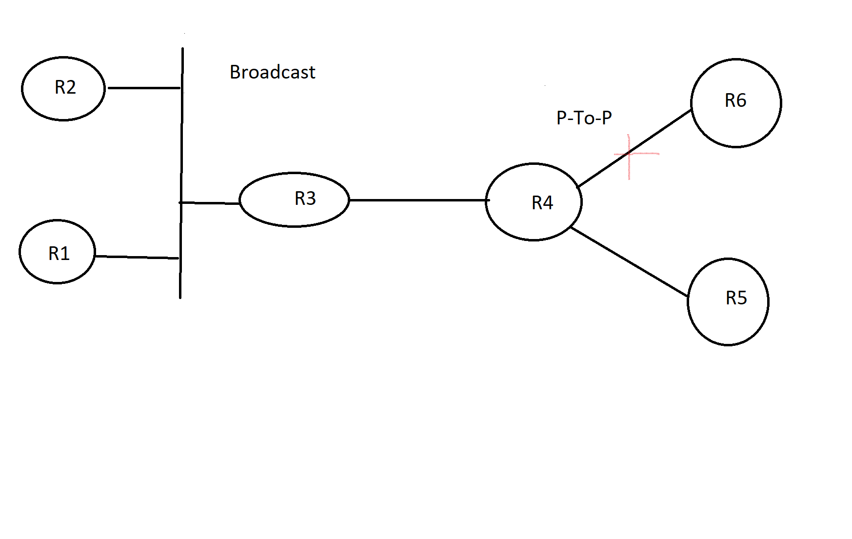
for the below drawing
If OSPF configured for all routers and assuming that link between R4 and R6 is failed and R4 not DR or BDR . How R4 will send update to R3 (the destination address for the update )? . Also How R4 will send update to R5 (Link between R4 and R5 is Point to point and what will be the destination address for the update )? the left side of the drawing are routers in the same broadcast network .(R1,R2,R3).
Appreciate your explanation in details
Thanks you
Hello Ramy
First of all it is important to realize that a DR/BDR election takes place per network segment only on multi-access segments. So in this case, the link between R4 and R6 does not have a DR/BDR election, and the link between R4 and R5 does not either. This is because, as you suggested, those links are point-to-point.
However, the link between R3 and R4 is I assume Ethernet, so between those two routers, R4 MUST be either a DR, or a BDR. Now DRs and BDRs will always listen on both 224.0.0.5 and 224.0.0.6. So if R4 is the BDR, it will send updates to 224.0.0.6. If R4 is the DR, it will send its updates to 224.0.0.5. In both cases, since R3 is always listening to both addresses, the update will reach it.
Now what if there was a third router on the segment and R4 was a DROTHER router? Then the update it would send would be to the 224.0.0.5 address, since it needs to send the update to the DR and BDR.
I hope this has been helpful!
Laz
Thanks for the explanation . excellent and clear one .
Hi,
For the frame-relay configuration, is it also possible to change the OSPF network type to broadcast and remove the neighbor commands?
I know you would have to make sure the hub becomes the DR using priority commands but if the frame relay inverse arp can emulate broadcasts, wouldn’t that just work?
Thanks,
Sam
Hello Samir
Yes, you can do this practically, and it will work. You just have to make sure you set up the frame-relay topology to “simulate” multicast and broadcast communication so that the adjacencies and the DR/BDR elections can take place. However, this is not best practice for several reasons:
frame-relay map command must be used to manually map IP addresses to the corresponding DLCI values and include the broadcast keyword at the end of each command. This allows both broadcast and multicast traffic to be forwarded.More on configuring frame-relay appropriately can be found here:
So in summary, it can be done, but typically should not be done, especially in a production network.
I hope this has been helpful!
Laz
Hi,
I just created a two router lab with one end as broadcast and the other non-broadcast (NBMA) but didn’t use a neighbor command (note, hello timers were changed to match), and the adjacency still formed.
When investigating how this was possible, I noticed that even if an interface is configured as OSPF non-broadcast, it still listens to the 224.0.0.5 multicast address. Is that correct?
Thanks.
Sam
Hello Sam
Yes, you’re correct. Even in an NBMA environment, OSPF routers will still listen for hello packets on the 224.0.0.5 multicast address. The difference lies in how they respond.
In a broadcast network type, OSPF routers will send hello packets to the 224.0.0.5 multicast address to discover OSPF neighbors and form adjacencies.
However, in an NBMA network, routers won’t send hello packets to the multicast address due to the non-broadcast nature of the network. Instead, they expect to be configured with the neighbor command to manually specify neighbors, and unicast hello packets directly to those neighbors.
In your case, the adjacency still formed because the broadcast side of your network was still sending hello packets to the 224.0.0.5 address, which the NBMA side was listening to. The NBMA side will respond to those hello packets with unicast hellos, forming the adjacency. Indeed, as you can see from this NetworkLessons note, in a pure NBMA scenario, you only need the network command to be issued on one of the two neighbors, and the adjacency will still form.
However, this is not a reliable or recommended setup, as the NBMA side won’t ever be able to initiate hellos, and must rely on the other neighbor to initiate the formation of the adjacency.
I hope this has been helpful!
Laz
A post was merged into an existing topic: OSPF Point-to-Point Network Type over Frame-Relay
Hi Laz,
I observed that even if one interface is in NBMA and other in P2M Non-broadcast, they are forming adjacency. Though they both should form neighborship if they are statically configured. Can you please explain this?
Sincerely,
Jugal Modi
Hello team,
I read somewhere that, “On an NBMA network, all Routers establish adjacencies only with the DR and BDR”
Is this true? Can you please explain.
Sincerely,
Jugal Modi
Hello Jugal
I went into the lab to check this out, because it sounded strange to me. I tried creating an OSPF neighbor adjacency between an NBMA and a P2MP Non-Broadcast network, but the adjacency did not come up. This makes sense because neither of these network types automatically send hellos to the broadcast address because they’re not broadcast networks.
However, if you configure the neighbor command on one of the two, then the adjacency forms. This is because the router configured with the neighbor command will begin sending unicast hellos to the configured destination. The neighbor receiving them will respond with unicast hellos to the source address. So with only one neighbor command configuration between the two, an adjacency will form.
Take a look at this NetworkLessons note that details the various OSPF network types for more info.
I hope this has been helpful!
Laz
Hello Jugal
Let’s take a step back and take a look at DRs and BDRs on any network type.
For a single network segment, OSPF will create adjacencies only between:
There is no adjacency formed between two DROTHER routers. This is the case wherever we see DRs and BDRs regardless of network type. That’s the very purpose of DRs and BDRs, to reduce the number of necessary adjacencies when you have multiple OSPF routers within the same network segment.
Now when it comes to NBMA networks, the only difference is that you must manually choose and define which routers will be DR and BDR using the ip ospf priority command. Typically, if you have a hub and spoke arrangement, the hub should be the DR and there should be no BDR. For more info on this, take a look at the following lesson:
I hope this has been helpful!
Laz
Hi,
Is it really necessary to learn OSPF Network types over frame relay?
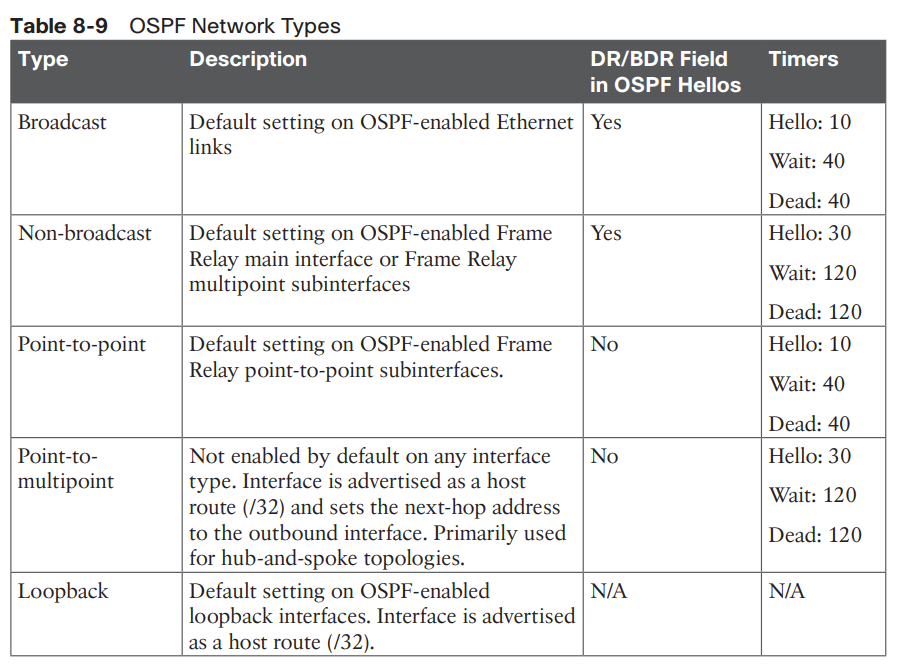
I understand most of it, yes it is nb and it is not multiaccess in the topology you gave etc etc, But it really confuses me, I looked it up from CCNP OCG and saw that network types explained in a really straightforward way (Like this →
In the exam are they asking network types with such a topologies presented in the lesson?
Best Regards
Hello Görgen
Frame relay is used because it is a Layer 2 technology that requires the use of some OSPF network types to allow OSPF to function. It is the easiest network to set up in order to test these network types. Indeed the table you shared is helpful and provides a summary of the various types of OSPF networks, but to see these in action, you need a topology like frame relay.
So although frame relay is no longer an official part of Cisco certification exams, it is necessary to lab up OSPF network types. Also, if you take a look at the table you shared, it also refers to frame relay… ![]()
I hope this has been helpful!
Laz