This topic is to discuss the following lesson:
Great explanation my friend. Thank you for making this tutorial very clear and concise.
Kyle
In the paragraph at the end, just wondering where you got the 1024 from for the sustained bits per interval?
The following commands however should give you the exact same result:
shape peak 128000
shape average 256000 1024 0
Hello Chris,
If you configure shape average and configure only the shaping rate then you get a Bc and Be:
R1(config-pmap-c)#shape average 256000
This shows:
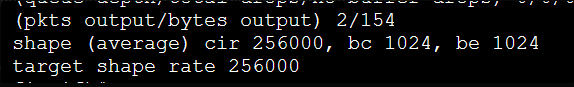
R1#show policy-map interface Fa0/0 | include bc
      shape (average) cir 256000, bc 1024, be 1024
So I only reconfigured it and set the Be to 0:
R1(config-pmap-c)#shape average 256000 1024 0
And we get:
R1)#show policy-map interface Fa0/0 | include bc
      shape (average) cir 256000, bc 1024, be 0
Hello Rene/Laz,
I have a few questions and I am going to use the below topology as the reference.
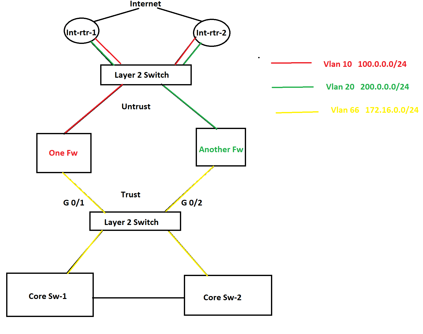
In this topology, there are two internet connections as you see in the picture and HSRP is configured between them. One router is active for one VLAN and another router is active for another VLAN is HSRP. There are two different firewalls for two different purposes. In this scenario, a lot of packet discards are being observed in the Trust zone and Untrust zone both because of bandwidth saturation. No port-channel can be configured anywhere as part of the requirement. Besides this, some TCP application traffic can not have any delay/slowness and those applications are sitting in the internet cloud. In this situation, I was thinking to configure QoS on port G0/1 and G0/2 and prioritize the applications. However, I was thinking to configure QoS policy based upon the ACL that consists of source and destination IP addresses since no device is marking these applications traffic anywhere in the network. What do you think about this? If you have any better solution, please let me know as well.
Now let’s move onto the second question. As you see in the diagram, there are two different VLANs in the Untrust zone which are using two different subnets of public IP address and they both are being advertised by both internet routers to the internet. I was thinking to configure GLBP in place of HSRP so both firewalls can use both internet circuits simultaneously. Note that both of the internet connections belong to the same service provider. What do you think about this solution? Again if you have a better solution, please let me know. Thanks in advance.
Azm
I just found out that GLBP will not help for load balancing in this case since only firewall will be ARPing to the GLBP Virtual IP. Therefore, we can take GLBP out of the picture. Instead, an equal cost static route will be effective. Thanks.
Azm
Hello AZM
Now when you say that you are seeing packet discards in the trust and untrust zone, I assume these drops are occurring on interfaces found on the firewalls? Where specifically is the bandwidth saturation taking place, on the interfaces of the firewalls?
Assuming that is indeed the case, since there is no marking anywhere in this network, then using source and destination IP addresses for applying a QoS policy sounds like a good idea. If your applications are such that source and destination addresses can sufficiently identify traffic that requires QoS then it looks good to me. However you wouldn’t be able to implement this on the G0/1 and G0/2 interfaces of the L2 switch, because it is L2. This would have to be implemented on the firewalls.
It is not always best practice to have a firewall implement QoS, because it is already doing filtering and many other high CPU usage functionalities. Whenever possible, offload some of these operations from firewalls to other devices. Although it makes configuration more complicated, you could implement QoS on the Core switches for traffic destined towards the cloud based applications, and on the Internet routers for traffic coming from the cloud based applications to your internal users. All of this assumes no other sources of traffic traversing the firewalls other than those shown in the diagrams.
As for your other question, yes you are right that GLBP will not help for load balancing. However, Cisco Nexus platform switches configured in HSRP configuration will always load balance between the two (or more) available links. This is the default behaviour, and actually cannot be modified. So if the Internet routers are Nexus devices, you’re good to go. If not, the best choice is to implement BGP dual homing and have each firewall connect to both routers.
I hope this has been helpful!
Laz
1 Like
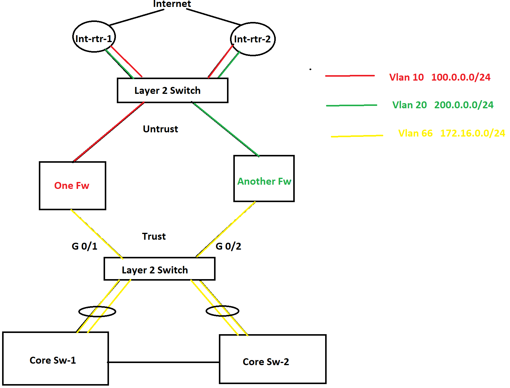
Thanks again for your reply. The layer 2 switch in the diagram is a 3850 switch and it has a port-channel with each core switch. Therefor, I do not see that much drops on the port-channel interfaces on any side. Most of the drops are being noticed at G 0/2 interface on the Layer 2 switch. Besides this, the core switch has multiple inbound interfaces. That is why I am kind of confused where I should put the QoS shaping policy. Because if I put it on the outbound port-channels on the core switches, it will not help because they are not encountering any bandwidth saturation. Since the core switches have multiple inbound interfaces, marking on multiple interfaces on the core switches will not be an idle solution. That is the reason why I was thinking to put a shaper on the G 0/2 interface on the layer 2 switch, but according to you, layer 2 switch interface can not do traffic shaping based upon IP addresses.
According to the requirement, putting a QoS policy on the firewall interface is not an option. Besides this, firewall interface is not encountering that much drop packets, because packets are getting dropped on the G 0/2 interface of the Layer 2 switch before it arrives at the firewall.
Question
===============
If a put a policy-map on an interface to mark traffic, would that policy-map come into play even if the interface does not experience bandwidth saturation? If an interface does mark packets even it is not saturated, then I can put a marking policy-map on the port-channels on the core switches going to the layer 2 switches and configure traffic shaper based on marking on the Gig 0/2 interface of the Layer 2 switch.
What DSCP values should I use to mark different applications?
What should I do for inbound traffic coming from the firewall to prioritize the same applications? Do I not need any QoS policy for the inbound traffic as well? If so, where should I put them?
Thanks again for your great help.
Azm
Hello Azm
First of all…
This depends on the IOS version being used, and what capabilities both it and the platform have. To verify this, you can always use Cisco’s feature navigator.
A policy map will employ its policies (such as marking packets) regardless of whether or not there is congestion.
Yes, you can employ that. This is for dealing with congestion on ports carrying traffic towards the Internet. The core switches can mark the traffic based on the applications being used, and the QoS mechanisms can be employed on the outgoing ports of the switches (towards the Internet).
Now if you are seeing dropped incoming packets on an interface, there is no way to employ any QoS mechanisms to alleviate such drops. As far as incoming traffic goes, you are at the mercy of the sending device. In your scenario, the interfaces of the L2 switch where the dropped packets are being seen are at the mercy of the senders which are the firewalls. This is why any QoS mechanisms should be applied to the sending device, which in this case is the firewalls. But as you say, this is not an option based on the requirements.
The only other option is to go further upstream to the other L2 switch or the two Internet routers to employ the traffic shaping/policing you need.
There are some best practices for what kind of traffic should be marked with what kind of DSCP values. This document is a good start for deciding on how to implement DSCP.
I hope this has been helpful!
Laz
Hello Laz,
Great explanation once again. I have two different types of applications. Therefore, I am thinking to mark one with AF31 and another one with AF21. What is your recommendation?
Thanks again.
Azm
Hello Azm
It all depends on the practical application. If the following criteria are met:
- If you are only using only two markings and nothing else will be marked on your network
- if no additional marked traffic will be entering your network
- if your marked packets are not entering other networks
If all of the above is true, then it doesn’t matter what markings you place on your packets. If there are two markings, you will prioritize each type in a specific way. You can have it AF11 and AF21 if you like. As long as you are reacting to each type of priority in the way which will deal with the congestion you are experiencing.
Now the best practices that are put into place are there in order to have a common method of prioritization so that in the event of the interconnection with other networks, the priorities and DSCP values being use are already normalized and compatible. If you are a completely autonomous system and there is no case where you will be sending marked packets to networks not managed by you, you can use any markings you like.
I hope this has been helpful!
Laz
Hi,
How can below configs give the same result? could you give in detail?
   shape peak 128000
    shape average 256000 1024 0
regards,
Hello Murat
The shape average 256000 1024 0 command here has the following values:
CIR = 256000
Bc = 1024
Be = 0
From this we can calculate Tc = Bc / CIR = 1024 / 256000 = 0.004 seconds or 4 ms.
So this means that with a value of Bc = 1024, Tc = 4ms, and Be = 0, we can reach up to the CIR, but even if you have idle time on the circuit, you will still only reach a maximum of 256000 bps, with no opportunity for bursting beyond that since Be = 0.
Looking at the shape peak 128000 command, we can see that the result will be the same. As explained in the lesson, the peak keyword simply means that the default Bc and Be are used (both equal 128000 in this case) resulting in a continuous shaping of up to 256000.
So both commands are the same.
I hope this has been helpful!
Laz
Hi,
I have question, You have mentioned below lines
At the beginning of the Tc we will only fill the token bucket with the Bc but because it’s larger we can “save” tokens up to the Be level. The advantage of having a bigger bucket is that we can save tokens when we have periods of time where we send less bits than the configured shaping rate.
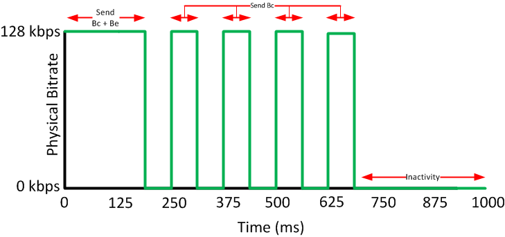
After a period of inactivity, we can send our Bc and Be tokens which allows us to burst for a short time. When we use a bucket that has Bc and Be, this is what our traffic pattern will look like:
But in the following diagram, I see you are sending Bc+Be bits in the very first Tc interval(0-125ms) which contradicts the above paragraph where you mention that we will start the bucket with only Bc. Am I missing something here ? Could you please explain a bit more?
Hello Aswin
Yes, you are correct, the wording at the beginning of the paragraph is not clear. You’ll notice that Rene states that because the bucket is "larger we can ‘save’ tokens up to the Be level, so initially, the bucket can be filled up to Bc+Be. The paragraph should read something like this:
“At the beginning of the Tc, because the token bucket is now larger, we can “save” tokens up to the Be level. The advantage of having a bigger bucket…”
Does that make sense? I’ll let Rene know to clarify that sentence.
I hope this has been helpful!
Laz
1 Like
Hello, everyone.
I am not quite sure if this is a mistake or if I am misunderstanding something here. Consider this example:
Rene’s explanation is as follows:
![]()
I am not quite sure about the “512 kbps” part.
If we don’t transmit anything, the BE bucket fills up with 1024 tokens/bits (BE) and no more than that. If we then start transmitting like crazy, we’ll be able to burst up to 1024 extra bits, but then the bucket will remain empty so we won’t be able to burst again thus we cannot just.. reach 512 kbps, can we? 512 kbps would be true if the BE bucket was constantly full but it would be emptied once the first TC passes.
Thank you.
David
Hello David
The PIR is defined as the rate at which the ISP will transmit your data whenever there is no congestion on the ISP network. The CIR is the guaranteed rate at which your data will be transmitted regardless of the state of the ISP network. It is the ISP that defines what “congestion” is. From the point of view of the customer, this just means that speeds up to the PIR will be available some of the time, while the CIR is guaranteed all of the time.
It doesn’t. Customer routers cannot dynamically detect ISP congestion. The point of using peak traffic shaping is that it is more appropriate when PIR and CIR are made available to you by the ISP. If the ISP gives you a CIR and a burst rate, then average traffic shaping is more appropriate.
The point of using peak traffic shaping is to be able to reach the PIR more often, thus taking advantage of it. This means that there may be times when your shaping will reach the PIR when at that time the ISP can only provide you with the CIR, thus losing packets. Yes, that will happen, but statistically speaking, the peak traffic shaping will deliver a more appropriate shaping for the use of CIR and PIR while minimizing packet drops due to the ISP’s policing.
I hope this has been helpful!
Laz
Hello Laz.
Thank you so much for the reply. I’ve recently figured this out and edited my message to another question if that’s okay with you ![]() Sorry for the late edit.
Sorry for the late edit.
David.
Hello David
It’s no problem that you changed your question, it’s an opportunity to answer more questions for other readers as well, so not to worry!
Concerning your new question, you’re absolutely correct in stating that the 512 kbps burst happens only once, after which the rate reverts to CIR (256 kbps). This is because:
- The Be bucket will not be refilled until another period of inactivity.
- The system cannot sustain 512 kbps without an ever-full Be bucket, which contradicts how token buckets work.
However, Rene did state that “we can spend both [the Bc and Be tokens] during a Tc which means we will shape up to 512 Kbps for a short time.” 512 Kbps is indeed achievable but only momentarily, in the first Tc after a period of inactivity.
So maybe it would be more precise to say that “we will shape up to 512 Kbps for a duration of one Tc”
I will let Rene know to consider making the clarification…
I hope this has been helpful!
Laz