This topic is to discuss the following lesson:
1 Like
Rene, you overviews are really good and easy to understand, on the above example there is no fa0/16 on switch A. Unless I’m not seeing right. Thanks
Hi Shaj,
Thanks! I just fixed it, it should be Fa0/17.
Rene
Hi rene , have u got any lessons on RSTP ??
M Q
Hi Muhammed,
For sure, here they are:
Rene
Hi Rene, how do you configure PVSTP?
Could you give me an example?
Hi Alberto,
PVST is the default on Cisco IOS switches. The example in this tutorial is PVST:
I only demonstrated VLAN 1 there but you can add VLAN 2 to it and take a look at it using the same commands, that’s a nice exercise ![]()
Rene
when switch B and switch A become root bridge the link between switch A and Switch C, blocked and also line between switch B and Switch C blocked. therefor the switch C there is not connection to the world. what happen to host connect to switch C?
Is this disconnection happen on trunk?
Hi Siavash,
Are you talking about this image?
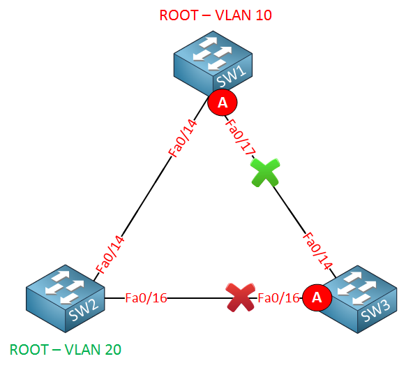
In this picture, Switch A FA0/17 is blocked for VLAN 20 and Switch C FA0/16 is blocked for VLAN 10.
When a host in VLAN 20 on Switch C wants to reach something connected to VLAN 20 in Switch A, we’ll have to go through Switch B.
Rene
What are the rules for Root Bridge election in PVST ? I mean going by STP rules in both cases Switch A should be selected as the Root Bridge. Can you explain that part as well.
Thanks,
K
Hi K,
The switch with the best bridge ID becomes the root bridge. The bridge ID consists of the priority (default value 32768) and the MAC address.
With the default settings, it’s up to the MAC address to determine which switch will become root bridge. This applies to all VLANs.
Rene
Karan,
I also wanted to add that in pvst+ you can change the bridge priority value by entering the command
spanning-tree vlan [id] root [ primary | secondary ] in global configuration mode.
This way controlling the election process
Hello friends,
About timers ,the stp 802.1d, pvst and pvst+ do they use the same semantic? Things change for rstp rpvst+
Hi Francesco,
Original Spanning Tree, PVST and PVST+ all use the same timers, adhere to the same standard (802.1 D), and all use the same BPDU packet version (zero). You are correct, that things change for RSTP and R-PVST+ (those use 802.1w, and BPDU packet version 2).
In case you were curious as to the difference between PVST and PVST+ … PVST is older and requires the Cisco proprietary ISL trunking mode to function, while PVST+ can function on 802.1Q trunks.
–Andrew
1 Like
Hello Rene, the answer you provided to Siavash on October 29th, 2015 I still think is not correct. You stated “Switch C fa0/16 is blocked for vlan20 and if a host wants to get to something on vlan20 in switch A, it will need to go through switch B.” That is not correct because fa0/16 on switch C is blocked, so to get to vlan20on switch A it will use the direct link fa0/14 to switch A. Also, if host in vlan20 on switchC needs to communicate to vlan 20 in switch B, it will need to communicate through switch A, because port fa0/16 on switch C is blocked for vlan 20.
Please let me know if this is correct or if I am missing something.
Hi Jose,
I see I had an error in my reply, just fixed it. Just in case let’s post the picture again here:
- The red cross means the port is blocked for VLAN 10.
- The green cross means the port is blocked for VLAN 20.
So VLAN 10 is blocked on the Fa0/16 interface of SwitchC and VLAN 20 is blocked on Fa0/17 on SwitchA.
When we want to go from SwitchC to SwitchA in VLAN20, we’ll have to go from C > B > A.
I should have used a green A (alternate port) in this picture to show the blocked port for VLAN 20 on SwitchA fa0/17 :).
Rene
Nicholas,
You are exactly right! With PVST, for say 50 VLANs, we are talking 50 different instances of STP running, each with its own root bridge, each sending out BPDUs–ridiculous! If you think about it, there is usually very few different STP topologies that an Enterprise might want to run to optimize their networks (usually about 3). So why in the world would you want 50 different possibilities with PVST? This is exactly why MST came about–group together all the VLANs that should share the same STP topology and save the resources.
1 Like
Hi Rene
The red cross means the port is blocked for VLAN 10, why do we need it blocked, as my understanding, there is no vlan 10 on SW3, so it was never be a loop.
is the block necessary for vlan10?
Thank you
Hello Hoan.
I believe that the first example where VLAN 10 exists only on SW1 and SW2 was used by Rene to indicate that Common STP would not be suitable for such a topology. He explains this in the video as well. When he begins the example of PVST, I believe he is indicating that VLANs 10 and 20 are configured on all three switches. This is also mentioned in the second video. However you are correct in that it hasn’t been made completely clear. I will ask Rene to take a look and make it clearer in the lab.
Thanks Hoan for your comments!
I hope this has been helpful!
Laz
Hi Laz & Hoan,
The first picture was only used to explain that the logical topology can be different from the physical topology, which is why we use PVST.
I understand this can be confusing so I added some extra text to explain that in the other examples, we use VLAN 10 + 20 on all three switches.
Rene