Thanks a lot as always Lazaros …
1 Like
Hi Rene,
This might be the very basic which is making me confused. When you are using topology of 2 switches to show loop, suppose if that 2 links are in etherchannel then what? Whether they will create a loop or not?
Hello Ritesh
If you configure two links to function as an aggregated port, then spanning tree will not be activated in such a case. The two (or more) links that are bundled into the etherchannel will be viewed and treated as a single link, so there is no logical loop there and thus STP will not be engaged.
I hope this has been helpful!
Laz
Hello @lagapidis,
the default STP mode was PVST+ until release 15.2(3)E. This may be added to the site as well
Source:
Hello sales2161
Thanks for that update, I’ll inform Rene as well!
Laz
1 Like
Thanks for sharing this @sales2161, I just added a note to this lesson.
1 Like
My pleasure!! @lagapidis @ReneMolenaar
1 Like
Hi Rene
Presumably, left to their own devices, switches would elect the same root bridge for all VLANs since the bridge priorities are global and not VLAN dependent. Therefore the concept of having different root bridges for each VLAN is something that has to be configured manually. Is that correct?
Thanks
Phil
Hello Philip
Yes, that is correct. When implementing PVST, the bridge ID that is used includes the extended system ID. In this case, you will have a bridge ID that looks like this:

Note that the bridge ID priority is composed of two parts, the bridge priority and the system ID extension. This simply translates to the bridge priority value configured on the device, and the VLAN number for that particular VLAN.
This is the reason why configured bridge priorities must be in multiples of 4096. So if you leave the default value of 32768, and you’re working with VLAN 25, then the bridge ID of each switch in that particular VLAN will be:
32768 + 25 + MAC = 32793 + MAC
This results in a unique bridge ID for each VLAN on each switch. If all switches are configured with their default settings, this still results in the same switch becoming the root bridge for all VLANs. So if you want to change the root bridge, you must manually configure the priorities appropriately.
I hope this has been helpful!
Laz
Rene,
I have very silly question and I believe I have some confusion in understanding VLAN. Here to understand PVST, you gave a example in which VLAN 10 was configured on SW1 and SW2. VLAN 20 was configured between SW1, SW2, SW3. Correct me if I am wrong: VLAN 10 on SW1 and SW2 means SW1 and SW2 have VLAN 10 individually and both the switches are connected using trunk? If yes, is that possible to connect three switches in trunking mode?
Hello Rajkumar
First of all no question is silly! What the diagram is describing is that VLAN 10 has been configured on both SW1 and SW2 and is allowed on the link between SW1 and SW2. The link between these two switches must be a trunk, since both VLAN 10 and VLAN 20 are being sent over it. Conversely, the connection between SW3 and the other two switches only carry VLAN 20, so these may be either access or trunk ports, but it really doesn’t matter for this example.
The point is that VLAN 10 is being sent only on the link between SW1 and SW2 while VLAN 20 exists on all three links between all three switches, creating a potential L2 loop.
Yes, it is possible to have all three links in the diagram in trunking mode, even if there is only a single allowed VLAN on the links between SW2-SW3 and SW1-SW3.
I hope this has been helpful!
Laz
Hi .
in which work environment we use PVST or PVST+ .
pervlan spanning tree it will make more work load for the network adminstrator/Engineer.
If there’s more than 500 vlans then he would be called Vlan Enginner .
I still haven’t reaqd RSTP or MSTP OR HSRP but just for the info which other service we use these days ? i think PVST might not be user friendly ?
Thanks
Hello Abdul
In order to understand PVST, you must understand that we are looking at a single physical topology, but multiple logical topologies (one for each VLAN). This means that any blocked port you may have, will be blocked for a particular VLAN. So, for each VLAN you have, you have a different set of root, designated and blocked ports, for each interface.
So in the lesson, you have a blocked port for VLAN 10 and a blocked port for VLAN20, each at different locations in the topology. If you have a total of five VLANs in your topology, for example, you can have up to five different sets of port states, applied for each VLAN within the topology.
I hope this has been helpful.
Laz
Hello Abdul
Just to clarify, PVST uses Cisco’s proprietary (and now out of date) ISL protocol for trunking, while PVST+ uses 802.1q which is the modern encapsulation used for trunks. So plain PVST should never be used unless you are limited to very old devices.
For networks with several dozen VLANs, PVST+ works fine, and should not overwhelm your network devices. As you approach 60, 70, and 100 VLANs, then you should consider an alternative.
Now if you have more than 500 VLANs then definitely MTP is preferable, and this is exactly what it has been developed for.
I suggest you go over these lessons, especially MTP, which will show you how useful it is for networks with many VLANs. RSTP, MTP, HSRP as well as PVST+ are all features that are used extensively in modern networks.
I hope this has been helpful!
Laz
Hi Laz,
Can you explain, How load balancing is being performed here ?
Hello Pradyumna
Imagine the topology from the lesson, with the following added hosts and router:
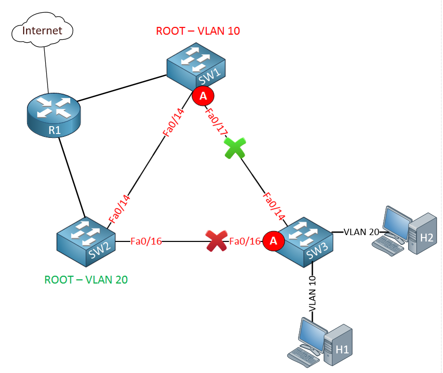
Per VLAN STP allows you to create a different STP topology for each VLAN. For VLAN 10, it is the link between SW2 and SW3 that is blocked. So host H1 which is on VLAN 10 would follow this route to get to the Internet:
- H1 → SW3 → SW1 → R1 → Internet
Conversely, for VLAN 20, it is the link between SW1 and SW3 that is blocked. So H2 which is on VLAN 20 would follow this route to get to the Internet:
- H2 → SW3 → SW2 → R1 → Internet
This way you can see that STP allows traffic to traverse both links, one for each VLAN. This is a much more efficient use of the available links as no link remains idle.
I hope this has been helpful!
Laz
Thanks Laz for explanation
1 Like
Hi Lazaros,
If I have three switches and vlan 10 20 and 30 are on all switches and they all use pvst+ will they by default each have different root bridges because they take into account 1st priority 2nd lowest vlan number and 3rd base switch mac address? Or lets say two switches had vlans 10 and 20 and one switch had vlan 30 would the root bridge per vlan be different switches? Lastly, since it goes priority, vlan number then mac address if a switch had a higher vlan number but lower mac address than another switch would the mac address overide its higher vlan number?
Hello Daniel
Let’s say you have the following topology:
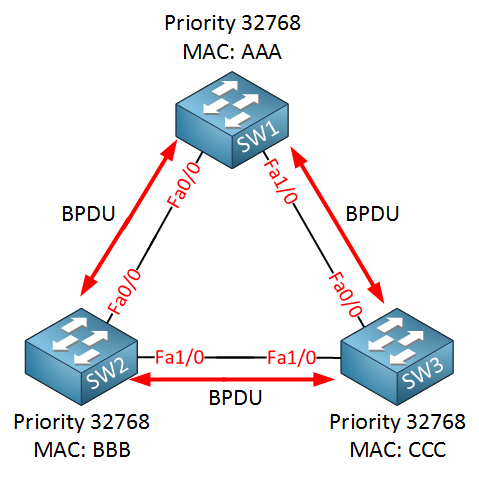
Now imagine that you have VLANs 10, 20 and 30 on all three switches, and the switches are connected with trunks that allow all three of these VLANs. Now if you’re running PVST+ then you are running a different STP instance for each VLAN. This means that a root bridge will be elected for each VLAN.
Now the root bridge election uses a combination of the MAC address, the assigned priority, and the extended System ID. By default, the priority is set to 32768. What is the extended system ID? It’s simply the VLAN for which the specific PVST+ instance is running. Let’s take SW1 for example. The bridge ID for the VLAN 10 instance of PVST+ is the following:
priority + vlan + MAC address = 32768 + 10 + AAA = 32778.AAA
(I’ll just separate the number from the MAC address using a . for convenience.) Now for the instance of PVST+ on VLAN 10, the priorities are:
- SW1 = 32778.AAA
- SW2 = 32778.BBB
- SW3 = 32778.CCC
So for VLAN 10, the PVST+ root will be SW1 which has the lowest bridge ID.
Now if you do the same exercise for VLANs 20 and 30, you will find that SW1 still becomes the root bridge. So by default, you will always have the same switch become the same root bridge for all PVST+ instances. and for this reason, it is always best practice to change the priorities so that different switches become the root bridges for the different instances of PVST+.
Note that even though the VLAN is included in the root ID, the bridge IDs of different instances, and thus different VLANs, are never compared for election purposes. The only reason that this arrangement is used is in order to ensure that the bridge ID is unique even if you have multiple VLANs.
I hope this has been helpful!
Laz
This was really helpful thank you!