Correct me if i’m wrong but with shaping you are changing the bandwidth on a link to slow down the rate at which traffic is sent across the link, but what about when you’ve a natural build up of packets then in that queue that may be coming from a link that is 100mb and your shaper is set to 50mbs, the packets that aren’t getting sent and that are waiting are going into the buffer/queue if i’m not mistaken? What about when this queue is full, do packets just start getting dropped then too? It almost defeats the purpose of a shaper then wouldn’t it.
The purpose of shaping is to limit the throughput of data over a particular interface, but to attempt to buffer exceeding traffic in such a way that it is not lost. This is in contrast to policing where excess packets are dropped. Because data traffic can be bursty, there’s a lot of time where the interface may be idle, and many times where it may be over the limit, in the course of a very short period of time (on the order of milliseconds to seconds). Shaping attempts to smooth out the rate at which packets are sent so that those idle times can be used to send some of the buffered traffic from those times where traffic exceeds the limit.
Even so, shaping does have its limitations. If too much traffic is arriving, queues will attempt to buffer it, but if they are filled to capacity, traffic will eventually be dropped.
The shaping you configure, the data rates you require, and the policies that will be applied depend on the requirements of your network. You must choose the best combination in order to server your data and your network most appropriately.
Hello, there.
The explanation of the policing and shaping is quite clear, however I’m a bit confused from the perspective of what exactly token represents. In the policing lesson you refer to the amount of token as amount of bytes in a packet. However in the shaping lesson you refer to amount of tokens as amount of bits. Can you please clarify this?
Thank you.
This is a good point you bring up. The token is simply a component of the mechanism used to calculate and implement shaping and policing. There is a difference however between the token bucket mechanisms used for policing and shaping. One of the differences is that for shaping, a the value of a single token is in bits, while that for policing is in bytes. You can find out more about the differences in these mechanisms at the following Cisco documentation:
Actually unable to understand that send traffic 50% of the time and pause for 50% of the time a/c to graph. actually want to know 50% of what time and will the traffic be sent at CIR rate or link capable of rate?
An interface on a device is not actually capable of transmitting data at speeds slower than the maximum interface speed. So a FastEthernet interface can only send traffic at either 100Mbps or 0Mbps. There is no “in-between” speed setting. So how do you employ traffic shaping? If you want to limit the speed to 50Mbps on such an interface, you would tell the interface to transmit for only half of the time.
This means that over a certain time period, an interface will transmit for half the time, and be idle for the other half. For example, we can tell an interface that for every second, it should transmit data at 100Mbps for 0.5 seconds, and be idle (0Mbps) for 0.5 seconds. Over time, you as the user would measure this as an average throughput of 50Mbps.
Now in the lesson, the bitrate of the physical interface is 128kbps, and if that interface transmits at full speed for 62.5ms and becomes idle for the next 62.5ms, and this cycle continues, then it is transmitting for 50% of the time. The result is that over a long period of time the average throughput is measured to be 64kbps, half of the physical maximum.
You can change the time periods to accommodate other speeds. For example on a GigabitEthernet interface, you can transmit at full speed for 200ms and remain idle for 800ms, and this would result in an average shaped speed of 200Mbps over that 1000Mbps link.
This is the essence of the mechanisms used for shaping.
Policing could be applied in both directions right?
Normally when you have a contract with your ISP they give you more bandwidth in the downloading direction than the uploading direction. Does this mean that the policing must apply in the ISP in both directions?
Let’ say we have a contract with 100 Mbps Download and 10Mbps Upload and an interface of 1Gbps connected to a customer.
On the ISP side, in the gigabit interface, we will apply the policing in the outbound to 100mbps and the inbound direction to 10 Mbps?
From the shapping point of view, on the customer side, if I have 10Gb on the lan side and 1 gb to the ISP side, always the shapping should be in the direction from the fast link to the slow link (outgoing direction of 1gb wan side)
When applying either policing or shaping, you must specify the direction of traffic flow you want to apply them in. This is done using the input or output keyword when applying the service policy to an interface. For example:
R1(config-if)#service-policy output SHAPE_AVERAGE
or
R1(config-if)#service-policy input POLICE_TRAFFIC
So yes, it is possible to specify a different policing or shaping rate per direction, and in case you do have an asymmetric connection, it is always best to shape according to the speeds you are provided with in each direction.
Yes, this is true for QoS in general. QoS is there to ensure that packets get forwarded according to the priority you’ve assigned them. If there is no congestion, that means that an interface is capable of immediately forwarding any frames/packets that arrive. In such a scenario, no buffering or dropping of packets is necessary thus no QoS mechanisms will be activated.
For policing and shaping, however, this is slightly different. What you are actually doing is changing how you define congestion. Shaping and policing will define an upper limit to the allowed throughput even if that upper limit is less than that of the physical interface.
In the same sense, if traffic doesn’t reach those limits you set, you are not experiencing congestion, thus no dropping or shaping features will take place. However, when those limits are reached (you could call that congestion) only then will you see shaping and policing activated.
So both shaping and policing will kick in only when the configured limits are reached, otherwise, neither feature is activated.
Yes, you are correct, my explanation was a bit simplistic. I have modified it to describe the situation correctly. Take a look at the newly edited post and let me know your thoughts.
so based on this and previous answer from Rene, we actually don’t know the Bc bucket size , is that correct? and possibly the Bc bucket size for shaping is greater than or equals the MTU of the interface( in other words, if Bc value >= MTU then bucket size = Bc otherwise, it equals the MTU ) at least this is the only explanation that make since to me, since if the Bc bucket size is equals Bc and the incoming packet is larger than the Bc, then the packet would’ve been dropped like how it is in police, or the packet will stay in the buffer forever because there is not enough tokens to get it forwarded at any time. I could be completely off here, but just trying to understand the details .
I understand how you get to this conclusion. But you must remember that the bucket size, as stated in the lesson, has a maximum size of Bc. It states:
The amount of tokens in this bucket is the Bc. Once the bucket is empty we can’t send anything anymore and you’ll have to wait for the next Tc. At the next Tc we will refill our token bucket with the Bc and we can send again.
This means that we can never send more than the Bc…it’s impossible to save tokens so that you can go beyond the Bc.
Now if the bandwidth we want to shape to is small enough, then yes, the bucket size may indeed be smaller than the MTU size. And actually, in the lesson, this is the case. Remember our Bc is 8000 bits? Well, that’s 1000 bytes which is less than the default MTU of 1500 which I assume is being used in the lesson.
So what happens then? Well, you would think that since you can’t take that many tokens out of the bucket (Bc is the maximum), the packet would stay in the buffer forever, but of course, that’s not the case. Similarly to what Rene mentioned in his post, it is likely that it will wait for a second Tc to send the whole packet together. This violates the bucket rule, but in order to keep the integrity of the packet, it may do so.
Now remember, this is a bit of speculation because this has to do with the physical methodology used to actually send the traffic over the wire and not the actual mechanism of shaping, so there is no way to use a debug command or something similar to see what is happening. As such, there is an alternative possibility. It may be that a shaper will actually send only 8000 bits in a single Tc, thus sending only part of the packet. It will simply continue sending the rest of the packet during the next Tc. There’s no rule that says that a packet must be sent intact within a single Tc. And remember this does not constitute fragmentation, since that requires a separate header on each fragment of the IP packet. This is simply sending a part of the packet in one Tc and the rest in the very next Tc. Does that make sense?
yeah that make total sense. I understand this is all speculation at this point and we actually don’t know what is happening at the hardware(ASIC) level. for me now at least for the sack of full understanding of the subject is that the bucket size will stretch temporarily up to the frame size and wait to fill just to accommodate the big frame that is waiting in the buffer.
Thank you Laz , this was really helpful and these forum discussions are great way to get full understanding of the subject.
One of the fundamental components of achieving traffic shaping is the Tc or time interval used. You see, a physical interface is able to send data at either its maximum speed or a speed of 0Kbps. In the lesson, we’re looking at a serial interface with a physical bandwidth of 128Kbps, so at any given point in time, the interface can send data at 128Kbps or at 0Kbps and not any values in between.
To achieve intermediate speeds, such as say 64kbps, traffic shaping will cause the interface to transmit at 128Kbps for 50% of the time, and 0Kbps for the other 50% of the time, thus giving an average over time of 64Kbps. To achieve a speed of 32Kbps, we would transmit at 128Kbps for 25% of the time, and at 0Kbps for 75% of the time.
To implement this practically, we need to define a time interval that will be used to define when to transmit and when not to transmit. The time interval must be sufficiently small in order to provide the “illusion” of a continuous flow of data. This time interval is called Tc or Time Constant or Commit Time.
Tc is calculated using the formula Tc=Bc/CIR. In the lesson:
Lets say i have applied CIR 100mbps by using shaping technic for my customer and they have around 50mbps drop, what happens to the 50mbp drop, does it goes to be buffered or dropped and how? could you please explain that accurately!!
and how could I know the size of the traffic exceeded or dropped?
In traffic shaping, if the traffic rate exceeds the CIR of 100Mbps, the excess traffic is buffered until it can be sent without violating the traffic contract. In your case, if your customer exceeds that by 50Mbps, the excess traffic is buffered and then sent when congestion reduces.
However, buffer sizes are finite, which means that they can eventually get full. If the buffer does get full, the excess packets will be dropped. This process is called Tail Drop. The size of the buffer determines how much excess traffic can be held before packets start getting dropped.
To know the size of the traffic exceeded or dropped, it is best to use a network monitoring tool that provides insights into traffic patterns and volumes. Network monitoring packages are by far the best choice, because they allow you to view the historical behavior or traffic on a particular interface where shaping takes place.
However, you can also use some CLI commands that give you some information that may be helpful. These include the show policy-map interface command. This will show you the number of packets that have been marked, dropped, or passed through the policy-map on the specified interface. Another way is to take a look at the counters on the show interface command.
Remember, the key to efficient traffic shaping is to configure your CIR and buffer size correctly according to your network’s needs and your expected traffic patterns. If you find that even with shaping you are getting tail drops, you may need to reconsider your network throughput capacities.
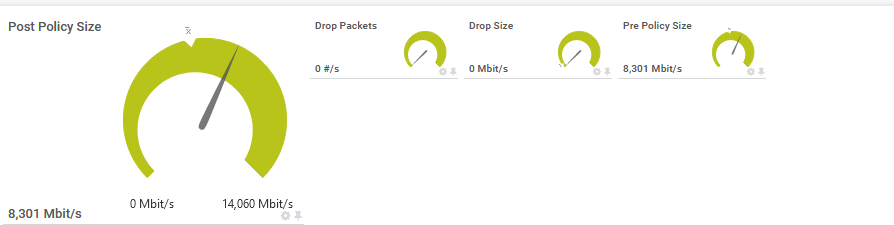
in the attached graph you see post policy and pre policy size is this the buffer size, also you have drop packet and drop size is this the drop size, could you help me understanding those parameters please.