In RSTP, the port role that corresponds to the blocking state is the Alternate port. An alternate port is one that is not Designated and not a Root port. It is one that receives a more useful (or superior) BPDU than the one it sends out. This port must continue to receive superior BPDUs in order to stay blocked. You can find out more information at this section of this specific Cisco documentation.
no need to be sorry! I am thankful that you help me with my questions!
One last question here.
“For STP, once there is a converged spanning tree, only the Root bridge sends BPDUs and other bridges just relay these BPDUs.”
The switches that just relay those BPDUs, do they send them out of all STP enabled ports, also blocking ones?
PVST and PVST+ are both proprietary protocols developed by Cisco
Some vendors, such as HP, Force10, Alcatel and others also support these STP protocols, however these are in general quite limited.
802.1D was defined without the use of VLANs, and so was 802.1w. In order to use these with VLANs, a separate instance of each protocol is run for each VLAN that exists on the network
One solution is to run STP (either 802.1d or 802.1w) one instance for every VLAN. If you have few VLANs, this will work fine. If you have many, Multiple Spanning Tree Protocol (MSTP) which is defined in IEEE802.1s which was later incorporated into 802.1Q-2005 is the way to go. It is an open standard used by multiple vendors to be able to create a per-VLAN functionality or groupings of VLANs.
Take a look at this Cisco documentation about RSTP
It states that in RSTP, all bridges generate BPDUs. Specifically it states that:
A bridge now sends a BPDU with its current information every “hello-time” seconds (2 by default), even if it does not receive any from the root bridge.
I decided to lab all this up and check everything with a wireshark in a virtual enviroment.
When it comes to classic STP everything was fine.
When it comes to RSTP, everythings seems to be fine (new frame, bdpu from everyone, topology change flood by everyone, uplinkfast,backbonefast) however in syn process, one switch sends the proposal once and once again, but never gets the acknowlegde back in any situation so it relay in old STP procedure.
My activation of rstp is just spanning-tree mode rapid-pvst command, is something missing in my config or is just its impossible to simulate this in virtual?
Keep in mind that the default version of STP that runs on Cisco devices is PVST+. It is based on the IEEE 802.1D standard with some additional Cisco extensions. Plain old STP (802.1D) is not actually available on modern Cisco switches.
Now the spanning-tree mode rapid-pvst command should be enough to enable rapid PVST+ as long as it is enabled on all switches participating in the STP. If it is not, then rapid PVST+ will revert to PVST+ with which it is backward compatible. If rapid PVST+ is reverting to PVST+ then you should check to make sure that plain PVST+ is not running on the same instance (VLAN) on another switch as the rapid PVST+ is causing it to revert.
“In RSTP, only non-edge ports that move to the forwarding state cause a topology change. This means that a loss of connectivity is not considered as a topology change any more, contrary to 802.1D (that is, a port that moves to blocking no longer generates a TC”
Can someone explain why a link failure is not considered a Topology change? How would link failures are detected by RSTP and what is their impact?
Keep in mind what the term “topology change” (TC) means in the context of the document. A topology change in general, such as the failing of a port, is of course a change in the topology, no question. However, as far as the TC flag goes in the mechanism of RSTP as compared to STP, the operation functions very differently. Just because it is only the non-edge ports that move to a forwarding state that cause a TC flag to be set does not mean that RSTP does not take such changes into account. As mentioned in the document you linked to, the TC mechanism was deeply remodeled.
Remember that in the original STP operation, the TC flag is set whenever a TC is detected in order to ensure a relatively quick flush of state information in the bridging table. Now RSTP doesn’t need such a quick flush due to the various changes in timers and operations, except in the event that a non-edge port moves to the forwarding state. It is just the way that RSTP now functions.
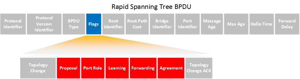
We knew that TC is flag LSB (2^0) and TCA is flag MSB (2^8)
Is it right to suggest that in this picture you should have from left to right
TCA (1 bit), Agreement(1bit), Forwarding (1bit), Learning (1bit), Port Role (2 bits), Proposal (1bit) TC(1 bit)
in the inverse order of the picture
Regards
This was a little confusing to me as well. The Least Significant Bit by definition should be the right-most bit while the Most Significant Bit should be the left-most bit when you’re looking at a string of bits. For example, the bold digit in the following string of bits should be the LSB: 00000000 however when looking at the frame above, it seems that they are placed the other way around.
I’m not sure why this is done, as when you look at other headers such as the IP address in an IP header, you don’t read it the other way around. For some reason, the BPDU flags are placed in the opposite order.
In any case, I haven’t been able to find a reason for this, but I believe it should be enough just to keep this in mind when you are studying and when you are writing your exams.
Hello Guys, I had a confusion in this topic in the topology when you start explaining the SYNC process between SW [1,2,3,4]. The First Topology says that SW1 is located at the top of all the switches. but in the next screenshots you start to say that SW1 is located at the left hand (when this is actually the SW3 shown in the first topology). maybe a correction is required. Please let me know. I hope to be helpful.
It’s been a while since I created this lesson. I think I moved SW1 to the left so the arrows with the proposal/agreement/sync looks a bit better. I understand the confusion though.
Quoting this from your explanation
“With the classic spanning tree a link failure would trigger a topology change. Using rapid spanning tree a link failure is not considered as a topology change. Only non-edge interfaces (leading to other switches) that move to the forwarding state are considered as a topology change. Once a switch detects a topology change this will happen:”
I have few questions on this.
1.If the port is moving to blocking state from forwarding state it will not generate TC. [Am I right here??]
2.What if the switch had two links to root switch and the active link went down will this not trigger the TC??
A TC will be generated only if a port goes from the blocking state to the forwarding state. This is the only time it will occur.
If the active link goes down, it will not send a TC (the link is down anyway and it can’t do so). But this will cause the blocking link to change state to forwarding, and it is this link that will trigger a TC. (blocking to forwarding = TC)
You can find more detailed information on how this functions and how RSTP compares to STP as far as topology changes go, at the following Cisco documentation.
Hi, simple question.
If there are 3 states in RSTP (Discarding, Learning, Forwarding) why in the CLI when the port is in not forwarding state, the status in blocking (BLK) like blocking, and not something like DIScarding? There is no Blocking in RSTP regarding the picture at the beginning of the lesson.
Unfortunately terminology is not something that remains constant. You are right that since RSTP uses the term Discarding as one of the three states. Even so, in the output of the show spanning-tree command, the state shown for Discarding is still BLK. This is just the choice that Cisco has made in how the output will be displayed. It makes sense to a point because anyone using STP or RSTP will be able to understand that the state of that port is one where ports are not active in the topology and don’t learn MAC addresses. We often use the term “blocking” instead of “discarding” even when using RSTP, or any type of STP for that matter.
I believe that Cisco decided to be more practical rather than more “correct” by using the term BLK to mean the same thing for either STP or RSTP. In the end, both a discarding port (RSTP) and a blocking port (STP) perform the same function anyway.