Hello Laz/Rene,
You explanation is awesome and clarified alot of my doubts. However, I have some doubts regarding the proposal/agreement handshake.
From what I understood, to participate in RSTP convergence, a switch must decide the state of each of its ports and when a RSTP enabled switches are powered on, the non-edge ports remain in designated/blocking or discarding state, correct?
These switches will start to exchange the configuration BPDUs of which the proposal bit is set to one.
Imagine that we have two switches SWA and SWB, and when these switches are powered on, both switches claim to be the root switch of the segment and they will both start exchanging BPDUs. SWA send a configuration BPDU with the proposal bit set to 1, when SWB receives this BPDU and see’s that it is a SUPERIOR BPDU, its considers the port that it receives this BPDU to be a root port, am I correct?
SWB will put all its ports to discarding state and sends its own BPDU proposal to its downstream neighbors, when it receives a responds from its downstream neighbors, it will the transition its root port to forwarding state and send a BPDU agreement to SWA set to 1 and proposal bit set to 0 . SWA ports will transition to forwarding.
I thought this superior BPDU was also to elect a root bridge or to see which device is having the best BID or.. to become the root switch? If otherwise, what’s the meaning of the Superior BPDU here?
Please could you clarify me on this ?
Thanks in Advance
Emmanuel
Yes, you are correct. When we talk about a superior BPDU, we mean a BPDU that has a better bridge ID (Priority + MAC). This will indeed be used to determine which switch will be the root bridge. This does not cancel out all of the other functionalities and operations that you described in your post, which all seem to be correct.
I believe you have a good understanding of the procedure!!
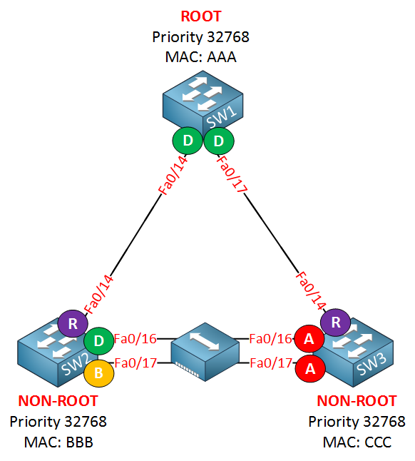
I do not understand really this - if you have 3 switches, and between 2 you insert a hub with 2 connected interfaces on each switch, why is it that 1 interface becomes a “backup” in RSTP? When you remove the hub, then you have 2 designated ports.
You say : “the reason that SW2 sees the fa0/17 interface as a backup port is because it receives its own BPDUs on the fa0/16 and fa0/17 interfaces and understands that it has two connections to the same segment. If you remove the hub the fa0/16 and fa0/17 will both be designated ports just like the classic spanning-tree.”
I did not get it, sorry. How the SW2 receives its own BPDUs?
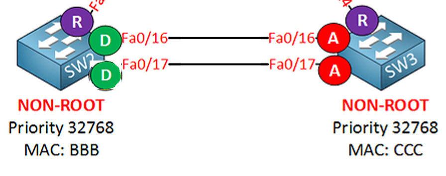
Now let’s assume that there is no hub, and that we have two links between SW2 and SW3. Each link is considered a separate segment, a separate broadcast domain. When we connect one switch directly to another, then there are only two devices within each of these segments. So we end up with two links, each of which is a separate segment, and each of which has two devices connected. This means that BPDUs that are sent on Fa0/16 of either switch are only received on Fa0/16 of the other switch. The same goes for Fa0/17.
This results in Fa0/16 and Fa0/17 on SW3 becoming alternate or blocked ports, and Fa0/16 and Fa0/17 on SW2 becoming designated.
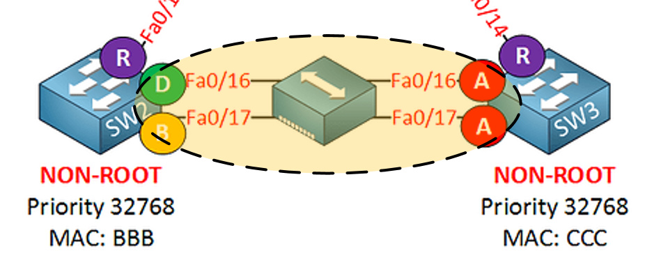
Now if we add the hub, we are now creating a single segment between the two switches in which essentially four devices (or ports) are connected. This means that BPDUs sent by each port will be received by the other three ports. For SW3, this change does not bring about a change in its behaviour. This is because SW2 has a better bridge ID than SW3, so all ports on SW3 connected to SW2 must be blocked.
On the SW2 side however, the switch realizes that both Fa0/16 and Fa0/17 are on the same segment (because of the hub). All BPDUs sent from either port will be received by the other port. This means that if both ports become designated, you have just created a layer 2 loop. It’s like connected ports Fa0/16 and Fa0/17 together directly with a UTP cable. So one of the two ports must become a backup port, which, like alternate ports, discard frames.
The key here is that the switch realizes that two or more of its ports are on the same segment, something that results in a layer 2 loop, and in a dysfunctional network.
thank you so much for detailed answer and for the picture as well, I could not copy it . I understand the loop on Layer 2 that we have just created, I do not understand still, why is it if we put hub between 2 switches, we create 1 collision domain. I know it might sound stupid, but I don’t get it.
In this case, if you have a BPDU (or any frame) exit Fa0/16 of SW2, then only Fa0/16 of SW3 will receive it. The same is true of Fa0/17. This is true because of the nature of switches. Each port on a switch creates a separate collision domain, thus eliminating any collisions when you only have two devices connected directly to each other. The result is that Fa0/16 and Fa0/17 on SW2 will independently become designated ports because the ports on the other end of their links are alternate.
In the case where you have a hub, you are creating a single collision domain to which all four ports are connected, like so:
What this means for this example is that if a BPDU (or any frame) exits Fa0/16 on SW2, the hub will receive the frame and send it out all of its ports, thus Fa0/16 and Fa0/17 of SW3 will receive it, and so will Fa0/17 of SW2.
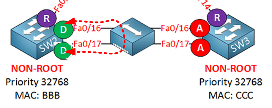
So, if Fa0/17 on SW2 becomes designated in such a topology, you would create an L2 loop like so:
So the role of backup port must be introduced to anticipate just such a topology.
Now having said that, you should never implement such a topology in your network, as it is inefficient and introduces the possibility of extensive collisions.
Thank you very much, Laz! I kiss your hands. The problem was, I was not familiar with hubs, we never talked about them into such depth in our course. That is why I love Networklessons. I am a perfectionist and I “simply must know” everything. Now I understand the whole thing.
Thank you very much again!
Hello Everyones,
I’m Félix, and i’d like to pass the brand new CCNP ENCOR this summer, but studying the stp these day i don’t understand something.
I have a quick question about RSTP, in this lessons it is written
“Rapid spanning tree will accept inferior BPDUs”
What does this means ?
is it correct to say inferior is BPDU with lower bridge ID ?
But what does effect to accept or not the inferior BPDU. It is not clear at all to me.
It’s great that you have set the goal of passing ENCOR in the summer, we wish you success and we’re here to help you along the way.
I understand the confusion in understanding this statement. Classic STP is configured by default to ignore any BPDUs that have a root bridge ID that is “worse” than the currently stored root bridge for that particular port. Such BPDUs may appear when a neighboring switch suddenly loses its uplink and claims itself the new root of the topology. By default, switches will ignore inferior BPDUs until the currently stored BPDU expires. Expiry will take place after a period of time equal to Max_age - Message-age. (For more info on STP timers, take a look at this Cisco Documentation). Typically, this can be up to 50 seconds.
Once the timers expire, and the current root bridge ID has been flushed out, only then will those inferior BPDUs be “accepted” and processed. This feature is there to stabilize an STP topology in situations where a switch’s uplink may start flapping. However, the downside is that this feature causes STP to take very long to reconverge.
Now, there is a feature called backbonefast which will cause STP not to ignore inferior BPDUs, but to process them. Specifically, backbonefast will skip the max_age timer, saving 20 seconds of wait time. You can find out more about backbonefast at this lesson.
Now RSTP will go one step further. It has been redesigned from STP such that it no longer uses timers, but a negotiation mechanism. When it receives an inferior BPDU, it will “accept” it and process it. Specifically, it will suspect that the current root bridge is down, so it will actively attempt to determine if this is so. If it cannot reach the root bridge, then it accepts the new inferior bridge ID as the root bridge, allowing RSTP to reconverge immediately.
Hello Lazaros,
First of all, thank you for your inducements and sorry for the time to respond.
Thank you so much for this quick, clear and very helpful answer. It is crystal clear now.
PVST just block any other BPDU and RSTP ask itself if something’s wrong by using the sync mecanism.
Yes, saying a BPDU is inferior is quite distabilizing because BPDU are based on Highest priority and lowest mac address, so hard to say whitch way it is going ^^
Have a nice weekend, at least a nice end of weekend.
Byyyyye
Very Well Explained Topic ! I tested in My LAB As well with same Topology - Tried to Block Ports , Increase Path cost , Increase/decrease Priorities to make a forceful elections etc - RSTP Convergence was so Quick. I used Debug command as well to see the process. Just need to read and repeat again and again after some time.
Just One thing - Backup and Alternate Ports are same thing right !!?
Got it - So Alternate Port is always there in sense - as Blocked port But backup port only appears if we use any Shared Medium and both Ports are going to same segment !!!
Great to hear that the lesson was helpful for you, and that you were able to replicate all of the content successfully!
To clarify, the Alternate port and the Blocked port are the same thing. It’s just a matter of terminology. Classic STP calls this port role “Blocked” while RSTP calls this port “Alternate”. They are exactly the same.
However, a backup port is different. It appears, as you say, if we use a shared medium for multiple ports on a switch within the same segment. The following link for RSTP clarifies these roles further.
You will have an article on Rapid PVST+, by the way… is it the same as Rapid PVST? or what does the “+” sign mean? I couldn’t find any useful information on the internet.
The use of the various titles can get confusing. Take a look at this post that clarifies the differences between the various versions of STP including the meaning of the “+” sign.
In classic STP only the root bridge generated BPDU, which were relayed by the non-root switches if they received it on their root port. what problem does RSTP solve by allowing root bridge and non-root switches to generate BPDU?
Classic STP not only depended on BPDUs sent in one direction downstream from the root to the rest of the topology, but it also depended upon timers. These timers were defied based on the required time needed to ensure that loops would not be created. RSTP has been completely redesigned from a timer based set of mechanisms to a negotiation.
A negotiation between switches involves communication in both directions, thus BPDUs are generated by both the root and by other switches in the topology. The negotiation is much faster in convergence, because decisions are made almost immediately during the negotiation rather than waiting for a predetermined period of time “just in case” new information is received.
This is the major benefit of the exchange of BPDUs in both directions.
Is it better for me config all the ports on the switch as “portfast”?
From what I understand, it’s better to have “portfast” isn’t it?
Is there any scenario that you don’t need portfast?
Thank you in advance.