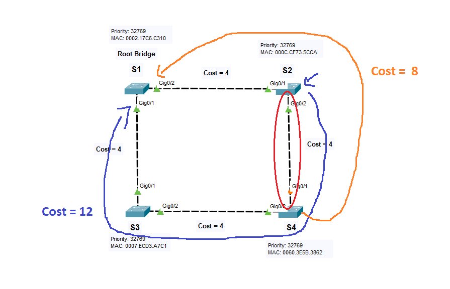
According to the theory, a designated port should be selected per each segment (link between two switches) and the one with the lowest total path cost to the root bridge between two ports becomes designated. In the image from the perspective of the GO/2 port of S2 the total cost to the root bridge is 12 and from the perspective of G0/1 of S4 the cost is 8. So, the G0/2 interface of S2 should be the port blocked? Can you explain to me what is the criteria that is being taken by which the port G0/1 of S4 is in a blocking state.
Thanks
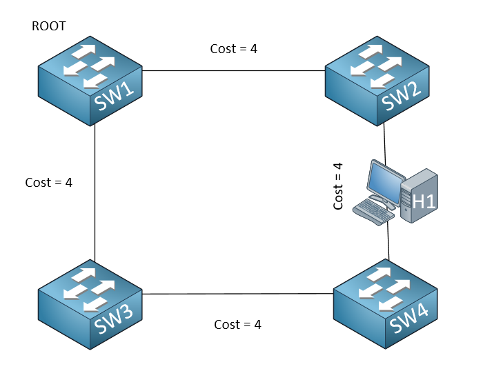
Hmm, not quite. At least not based on your diagram. You should think about it this way.
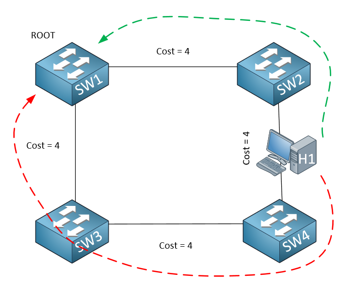
In order to determine which port between SW2 and SW4 is designated, you should imagine placing an imaginary device on the link between the two switches like so:
I have a doubt about this excerpt from this lesson :
02:51:09: STP: VLAN0001 heard root 32769-fa16.3e5d.b4a0 on Gi0/2
The above, SW2 heard SW4 claiming to be the Root Bridge. But i always have thought in STP (not RSTP) only DSG port sends BPDUs. My question is how SW2 receives SW4 BPDU if in theory, SW4 Gi0/1 (towards R2) is a root port so it wouldnt send any bpdu to R2.
In standard IEEE 802.1D STP, all active ports send out BPDUs except root ports and blocked ports. So designated ports are able to send BPDUs while root ports and blocked ports only receive BPDUs.
Now having said that, in the situation you are describing in your post, the Gi0/1 interface of SW4 sends out a BPDU that is received on Gi0/2 of SW2. So in this scenario, at this point in time, SW4 believes itself to be the root bridge.
All of the ports of a root bridge are, by definition, designated ports. Therefore, the BPDU that’s sent from SW4 is sent from a designated port, so it does indeed conform to the rules of STP. Does that make sense?
I’ve tried a STP 802.1D topology , issued debug spanning-tree bpdu receive in the Root Bridge and indeed it has never received a bpdu from SW2 root port until ive changed the bid priority in SW2 therefore it see itself as the root bridge and triggers a BPDU to its former root port towards SW1.
But remain one doubt about blocked ports. I’ve also issued debug spanning-tree bpud receive on SW3 (root port towards SW1 and blocked port towards SW2) , both ports only receives bpdu and never send bpdu. In what situation a blocked port would send a bpdu ? in the same situation described above ? i mean, by example shutting down RP to SW1, the SW3 port towards SW2 will trigger a TCN BPDU and later on will come the RP.
I guess in a stable topology, designated ports only sends bpdu.
First of all, thanks for sharing your experiment results with us, that is very helpful.
Now concerning your question about blocked ports. In the original IEEE 802.1D, blocked ports do not send out BPDUs, but they only receive them. I have corrected my post above as well…
So the debug that you ran on the blocked port that showed that it only received BPDUs is the correct and expected behavior.
I didn’t understand the formula max age -message age = the time which BPDU will expire.
like isnt max age based on the seconds? however we count message age not based on seconds but non-root swittches it passed. So how we can even subtract them?
Indeed, it seems a bit confusing at first. In STP, both Max Age and Message Age are expressed in seconds, although they are determined in different ways.
Max Age is a configurable value that indicates the maximum time a BPDU is considered valid. The default value is 20 seconds, but it can be adjusted based on network requirements.
Message Age, on the other hand, is not directly based on real time, but rather on the number of switches a BPDU has passed through. Each time a BPDU is forwarded by a switch, the Message Age is incremented by 1 (which is equivalent to 1 second). So, if a BPDU has passed through 5 switches, its Message Age is considered to be 5 seconds. It’s similar to the way the TTL in IP works.
Now, when we say “Max Age - Message Age”, we’re calculating the remaining time before the BPDU is considered expired. For example, if Max Age is 20 seconds and a BPDU has a Message Age of 5 seconds (i.e., it has passed through 5 switches), the BPDU will be considered valid for another 15 seconds.
in Shutting GigabitEthernet0/1 on SW1 situation , isn’t SW4 should consider itself a root bridge? and then after Gi0/2 on SW5 reconverged to forwarding mode It should again supersede itself to SW1 as root bridge?
But in the debug screenshot of sw4 First it heard SW1 as root bridge for 02:51:10, but in that time SW2 still is hearing SW4 as root in the SW2 screenshot so I guess the topology has not been converged yet. So how even SW4 hear SW1 as root?
another connected question is, you make a sentence like this “Within the same second, SW2 has sent the superior BPDU from SW1 so for a short while, SW4 reconsiders Gi0/1 as its root port.” how SW2 sent superior BPDU from SW1 as it can not hear sw1 bpdu over Gi0/1? Isn’t SW4 should hear it via SW5?
You’re right. In the debug info for SW4, we see initially a BPDU received on Gi0/1 from SW2 indicating that the root bridge is SW1, and that the local root port is Gi0/1. But then SW5 sends a superior BPDU which is detected on Gi0/2 of SW4, so the new root port becomes Gi0/2. Indeed in the debug of SW4 we see no indication that SW4 ever considers itself root bridge.
Conversely, we see that SW2 does consider SW4 the root bridge because it received a superior BPDU from SW4.
I will let Rene know to take a look and see if there is any clarification he can make to the lesson to make it clearer what is going on.
If you connect an Ethernet cable from one port onto another port on the same switch, the switch will detect a L2 loop, and will block one of the two ports. How does it decide which one? Well, the criteria that are checked are the following:
The port that will be blocked is the one that has:
highest path cost to the root bridge
highest bridge ID
highest port ID of the sending device
highest port ID of the receiving device
Regardless of whether or not the switch is the root bridge, all of these will be checked. Because both ports are on the same switch, both ports are receiving and sending ports. So ultimately, it is the port with the highest port ID that will be blocked.
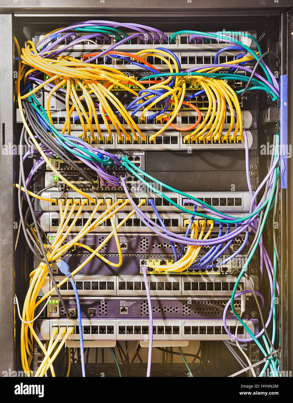
Your question is a very good one. It can happen more often then you think. If you have a rack that looks like this, no matter how tidy you keep it, if you’re not careful, you may connect one switchport to another on the same switch.
On switches like Cisco’s, this is not a problem because one of the ports will be blocked. However, I have had a case where someone made such a connection on a small cheap unmanaged switch that didn’t have STP, and the whole network segment went down, and it was quite difficult to track down the specific link. But in any case, that’s how it works…
Thank you so much for the response. Yes, I got the point. So basically, whatever is the case, STP will follow the required checklist to solve the looping, if it is active in the topology, correct?
Additionally, I was going through OSPF lectures and had some doubts:
Question 1:
How does OSPF avoid control plane looping? I did find an answer, however, couldn’t understand it clearly.
To be specific it is point number 2 and 3. The question is how? Is there any specific bit, flag?
Answer :
Area Border Router (ABR) is a router that has at least one interface in Area 0 and this interface is not in a down state. ABRs will set the B (border) bit in their router LSAs to signal other routers in the same area of their ABR status. Only ABRs are allowed to generate summary LSAs and inject them in the attached areas.
ABRs expect summary LSAs from Area 0 only. This means there should be at least one adjacency in a FULL state built over an Area 0 interface. If an ABR has such an adjacency, it will ignore summary-LSAs received over non-backbone areas. These LSAs will be installed in the database, but will not be used for SPF calculations.
ABRs will accept and use summary-LSAs learned over non-backbone area they do not have a FULL adjacency built over an Area 0 interface. It is safe to do so, since the ABR will not be able to flood the summary back into Area 0 creating routing loops.
Question 2:
Why p-bit is unset when NSSA ASBR is itself a NSSA ABR? Like how would the process be let’s say if we have two NSSA ABR and I redistribute loopback 1 (10.1.1.1) into one of the NSSA ABR. It will start acting as NSSA ASBR now. Correct? So will LSA 7 be generated by that particular ABR/ASBR or not? I am totally confused about the scenario.
Hmm, it depends on what you mean exactly when you say “control plane looping.” Another phrase for this is “lack of OSPF convergence.” The term “control plane” indicates that OSPF messages are being sent continuously and looping throughout the topology, which indicates a lack of convergence. This is something different from routing loops which direct user traffic to loop indefinitely throughout a topology. Such loops in this context may be considered considered data plane loops. But these phrases aren’t standardized, so that’s why I’m clarifying it here. Is this what you are referring to?
The three points that you mention as methods of mitigation of loops are used to mitigate against routing loops, not lack of OSPF convergence.
What points 2 and 3 are saying is that αn ABR will normally only accept and propagate summary routes from Area 0 to ensure a consistent and loop-free routing environment. By limiting the propagation of summary routes from Area 0 only, OSPF ensures that routing information is disseminated in a hierarchical manner. This reduces the complexity of route propagation and the risk of loops.
However, if an ABR loses all full adjacencies with Area 0, it can accept summary routes from a non-backbone area as a temporary measure to maintain network connectivity. This behavior is designed to preserve the integrity and stability of the OSPF routing domain while providing flexibility to handle exceptional situations where backbone connectivity is temporarily lost.
Take a look at this lesson that talks about he P-bit in detail:
If you still have questions after going through this, let us know and we’ll address them.
Hmm, I’m not sure what you are referring to when you mention a TCP Trap. Can you give us some more details? How is this TCP trap related with BPDUs which are STP entities which operate at Layer 2?
Give us some more info so that we can respond to your question. Thanks!
Ah, ok I see, no problem. The topology change is indicated by a flag that exists within the header of the BPDU. Take a look at this NetworkLessons note that talks about the contents of a BPDU in more detail. If you have any other questions, let us know!